Thursday, July 17, 2025

Simulation Solutions for the Structural Integrity of Chip Packages

The shift toward three-dimensional integrated circuits (3D-IC) marks a transformative design leap in semiconductor technology, driven by the demand for higher performance, smaller form factors, and lower power consumption. However, this innovation introduces significant challenges in maintaining structural integrity, which is critical for device reliability. Semiconductor engineers must understand the engineering challenges affecting chip package structural integrity in the context of 3D-ICs, and their solutions.

The Driving Factors in 3D-IC Adoption
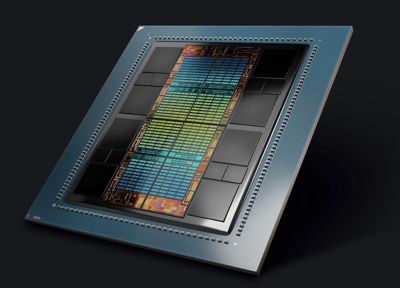
amd-mi300x.jpg

AMD MI300X

The adoption of 3D-ICs is driven by key business factors, such as the growing demand for miniaturization, market trends in consumer electronics, and the Internet of Things (IoT), which favor compact devices with enhanced functionality. Performance needs are also a significant driver, with 3D-ICs offering reduced signal latency and increased bandwidth compared to traditional printed circuit boards (PCBs). With these modern-day must-haves, energy efficiency is critical, as die stacking minimizes interconnect lengths and reduces power consumption — a key requirement for mobile and edge devices. Finally, advanced applications in AI, 5G, and the automotive industry require high computational capabilities, making 3D-ICs essential for meeting these evolving demands.

2-5d-ic-layout-including-3d-high-bandwidth-memory-hbm.jpg 

A 2.5D-IC layout including 3D high-bandwidth memory (HBM)

Solving Engineering Challenges in IC Development

While electronics reliability and signal and power integrity (SI/PI) have been cornerstones of IC design with well-established techniques, the advent of 2.5D/3D-ICs introduces unprecedented thermal and structural challenges. Mechanical and thermomechanical stresses during manufacturing and operation pose significant risks to structural reliability, which traditional design methods fail to meet in terms of increased model complexities affecting design cycles and yields.

The vertical stacking of chips generates high stress, increasing the risk of warpage or cracking. Additionally, dense stacking exacerbates heat buildup, which requires advanced thermal management solutions. Any minor warpage can cause assembly defects, leading to low yields. Therefore, the 3D-IC structure must be flexible enough to minimize stress while ensuring that any warpage remains within the prescribed limit.

Interconnect reliability also emerges as a critical factor, with through-silicon vias (TSVs) and solder microbumps needing to withstand stress, and fatigue due to thermal cycling. Reduced dimensions of microbumps and copper pillar bumps increase susceptibility to cracking and fatigue failure. Additionally, the complexity of multiphysics simulations involving thermal, mechanical, and electrical coupling presents computational challenges that demand robust tools and methodologies.

2-5d-model-mesh-in-ansys-mechanical-software.jpg 

2.5D model mesh in Ansys Mechanical software

Discover Simulation Solutions

The semiconductor industry requires workflows and solutions that bridge the gap between semiconductor design engineers and physics analysts. Effective collaboration between these roles is essential but complicated by issues such as encrypted file handling, multi-tool environments, intricate feature modeling, and high-fidelity solutions.

To address the collaborative and technical challenges in 3D-IC structural integrity, solutions like Ansys Redhawk-SC Electrothermal software provide advanced capabilities to simulate and analyze the thermal and mechanical behavior of designs. This tool is primarily used by semiconductor engineers for quick power integrity and thermal and stress signoff, enabling them to evaluate heat transfer, temperature distribution, and thermomechanical stresses efficiently. This tool enables users to model the geometry and material properties of 3D-IC components, including the silicon interposer, multiple dies, and interconnects. Additionally, RedHawk-SC Electrothermal software equips semiconductor design engineers — who may not be analysts — with an intuitive workflow to rapidly assess stresses and warpage, ensuring designs meet performance and reliability specifications for quick signoffs from a single tool.

For detailed structural and thermal design, semiconductor packaging teams rely on industry-leading physics tools like Ansys Mechanical software, the Ansys LS-DYNA  solution, and the Ansys Icepak application. Mechanical software enables in-depth heat transfer and stress analysis, helping engineers optimize material selection and structural design to minimize warpage and enhance reliability. Design optimization strategies — like reducing TSV density in high-stress areas and using high-fidelity best-in-class structural solvers like Ansys Mechanical APDL (MAPDL) and LS-DYNA software — further mitigate structural risks and enhance overall reliability by doing multilevel sub-modeling.

The Icepak CFD-based thermal analysis tool helps package design engineers model heat dissipation and cooling strategies, ensuring thermal integrity across complex 3D-IC architectures. It also helps capture accurate heat transfer boundary conditions of the 3D-IC that can be used by Redhawk-SC Electrothermal software for a detailed thermal stress analysis. A simulation-driven design approach — leveraging tools such as Redhawk-SC Electrothermal software, Mechanical software, and Icepak software — facilitates the early prediction and resolution of reliability issues, ensuring robust semiconductor packaging designs.  

Different customers have unique simulation workflows, and Ansys excels at addressing these needs with its open and interoperable tools. This enables semiconductor designers and analysts to collaborate effectively, accelerating design cycles while delivering high-fidelity solutions for electrical, thermal, and structural signoffs. 

AI-driven thermal analysis is revolutionizing semiconductor design by enabling faster and more precise hotspot detection. AI-powered electrothermal modeling predicts hotspots in advance, enabling adaptive meshing to refine the resolution only where necessary. This approach significantly speeds up analysis while ensuring high accuracy.

typical-workflow-for-evaluating-the-impact-of-thermal-and-warpage-on-si-pi-in-3d-ics.jpg 

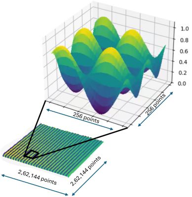
Typical workflow for evaluating the impact of thermal and warpage on SI/PI in 3D-ICs

Recent examples of structural integrity solutions in 3D-ICs demonstrate the impact of advanced simulation tools. Toshiba leveraged simulation technologies to enhance the reliability of automotive semiconductors by identifying and addressing critical failure mechanisms early in development. Similarly, a leading semiconductor company utilized Icepak simulations to optimize heat dissipation in a stacked-die configuration, achieving improved performance while maintaining reliability. TSMC leveraged Mechanical structural finite element analysis (FEA) software to simulate mechanical stresses induced by thermal gradients in 3D-ICs. This solution has been demonstrated to run efficiently on Microsoft Azure, ensuring rapid turnaround times for today's large and complex 2.5D/3D-IC systems. It effectively addresses the unique multiphysics requirements, enhancing the functional reliability of advanced designs built with TSMC’s 3DFabric — a comprehensive suite of 3D silicon stacking and advanced packaging technologies.

3D-ICs: Innovation, Collaboration, and Reliability

As 3D-IC technology continues to advance, the focus will remain on key areas such as predictive analytics, in which AI-driven simulations are used to identify potential failures before fabrication to enhance design reliability. Collaborative ecosystems will also play a vital role, fostering closer partnerships between EDA tool providers, material scientists, and design engineers to drive innovation. Additionally, ensuring seamless data transfer across tools like Redhawk-SC Electrothermal software, the Icepak application, and Mechanical software will be crucial in streamlining multiscale workflows. Ultimately, maintaining the structural integrity of 3D-ICs is essential for their successful integration into modern electronics. By leveraging advanced engineering solutions and simulation tools, including Redhawk-SC Electrothermal software, the Ansys Mechanical solution, the LS-DYNA application and Icepak software, the industry can unlock the full potential of 3D-ICs to meet the stringent demands of reliability and performance.

Learn more about how Redhawk-SC Electrothermal software can help with your 3D-IC needs. 

The Autonomous Software Powering the Future of Aerospace and Defense

If you were to take apart an autonomous system, what would you find? You’d quickly see the hardware components that enable the autonomous system to perform its mission, such as sensing and perception systems. You would not, however, be able to see a part of the system’s design that is equally important: software.

The software used in autonomous systems in the aerospace and defense (A&D) industry is both incredibly complex — sometimes requiring developers to continuously and rapidly validate billions of lines of code — and quickly becoming more diverse. As such, this software can vary greatly depending on the type of autonomous system you’re working with.

Despite this diversity, there are a few core software types used in autonomous systems, which range from embedded software and control systems to connectivity and communication software. These key software types are:

  • Data fusion, sensor fusion, and processing software for improving data quality and extracting actionable insights
  • Decision-making and planning software to automate those tasks in real time
  • Command, control, and intelligence (C2I) software for enhancing a system’s ability to analyze complex data and provide decision support
  • Execution and control software for learning from ongoing operations and then adjusting execution strategies for optimal performance
  • Connectivity software for ensuring that autonomous systems can connect and share important information and data with other systems via transmitter-receiver (Tx/Rx) devices
  • Network quality, cloud, and edge computing for building robust, high-quality communication networks with optimized system performance, secure connections, and scalability
  • Middleware and glue code for enabling different connectivity systems to have full interoperability and seamless integration
  • Chip design and certification for ensuring that all the elements mentioned above can achieve sufficiently high and reliable performance

Let's briefly discuss the goals and challenges of working with autonomous software.

aerospace-software-systems

What Are the Objectives of the Software Used in Autonomous Systems?

No matter its specific functionality, all the software lying beneath the surface of an autonomous system in the A&D industry needs: 

  1. High levels of responsiveness and performance to work in the dynamic and challenging environments that A&D systems exist within 
  2. Seamless connectivity and the ability to communicate with external software and networks
  3. Proper integration with the hardware as part of the overall autonomous system
  4. Actionable data from sensors and artificial intelligence (AI) for real-time data processing, adaptive decision-making, and intelligent control 
  5. The ability to be scalable as well as to quickly grow and evolve, which can involve the use of continuous integration/continuous deployment (CI/CD) and over-the-air (OTA) updates 

These goals hold true no matter the type of software you are developing.

engineers-working-on-aircraft-design

Key Challenges in Software Development: Integration and Standardization

As autonomous systems in the A&D industry become more complex, their software must also rapidly evolve to match this pace of innovation. To do so, software developers need to overcome a few persistent challenges.

First, all software must be compliant, achieve all needed certifications, and have proper identification of failure modes. With autonomous technology changing quickly, this has become a major obstacle due to the lack of dedicated standards and common practices like use of in-house and third-party tools. At the same time, autonomous software also needs to achieve improved processing power, performance, and optimized size, weight, power, and cost (SWaP-C).

Another hurdle engineers face is ensuring proper software integration, which is a particularly complicated and costly part of the development life cycle. Adding to this is the fact that integration is multifaceted and must occur between the embedded software of a single system and between a system and external systems.

Conquering all of these challenges will not be easy, but it is an integral part of creating an accurate, safe, and effective final design. 

technology-and-aviation

Achieving New Levels of Innovation With Digital Engineering

Looking ahead to the future generations of autonomous software, we will see systems that are increasingly responsive, dynamic, robust, safe, and able to form standardized connections. To achieve this future, researchers, engineers, and developers are increasingly turning toward digital engineering.

With digital engineering, engineers gain the ability to understand how their autonomous systems will perform in the physical world by using a trusted virtual model-based environment. Further, digital engineering enables software to be developed while improving performance and accuracy; ensuring safety, reliability, consistency, and compliance; increasing interdisciplinary collaboration and communication; and reducing time and costs — better helping innovators usher in the next generation of autonomous software.

Ready to learn more about the use of autonomous technology in A&D? Download the "Designing Optimized Software Stacks for Autonomous Systems in Aerospace and Defense" e-book and visit Autonomous Systems for A&D.

Scaling Quantum Computing Research to a New Milestone

Ansys computational fluid dynamics simulation scales to 39 qubits with NVIDIA CUDA-Q on Gefion supercomputer.

Computational fluid dynamics (CFD) simulations have become indispensable across aerospace, automotive, energy, and process industries. As design cycles accelerate and fidelity requirements rise, the size and complexity of CFD models continue to expand, driving demands for ever-greater memory capacity, finer spatial resolution, and faster turnaround times. Ansys has long led efforts to address these challenges, pioneering high-performance solvers and integrating high-performance computing (HPC) and artificial intelligence (AI) to accelerate convergence and reduce computational cost without compromising accuracy.

The Ansys CTO Office is actively engaged in researching quantum algorithms to accelerate partial differential equations (PDEs), with an initial focus on CFD due to the availability of well-established benchmarks from the research community. We have adopted the NVIDIA CUDA-Q open-source quantum development platform to build our quantum applications stack, enabling scalable GPU-based algorithm simulations in a noiseless environment today and seamless execution on quantum hardware as we transition beyond the noisy intermediate-scale quantum (NISQ) era. Once we identify an algorithm that scales to industrial sizes and complexity, we will advance to hardware demonstrations as the next step in our research. This iterative process enables us to converge on the most effective methods for quantum readiness.

The NVIDIA CUDA-Q platform’s flexibility in developing hybrid quantum-classical workflows and GPU-accelerated quantum circuit simulations has played a key role in enabling us to study how the algorithms we explore will scale.

Quantum Computing Meets CFD

Quantum algorithms seek to carefully exploit novel ways that information can be processed when encoded in quantum systems. Quantum systems seem intuitively appealing for computationally demanding CFD simulations, particularly:

  • High-dimensionality: Unlike classical bits, quantum bits — known as qubits — can encode data that scales exponentially with their number. The addition of every qubit doubles the addressable data space. By representing an entire computational grid, potentially encompassing billions of points, into the amplitudes of a quantum state, quantum computing provides access to a vastly larger solution space. In fact, as demonstrated later in this blog, we solved a problem involving 68 billion grid points using just 39 qubits!

  • Parallel global updates: Quantum computing offers the possibility of iteratively updating data to evolve through timesteps commonly used in CFD as coherent global operations performed in a single circuit execution. This would allow simultaneous updating of all gridpoints rather than through iterative kernel launches.

However, successfully employing these properties for useful CFD applications is far more nuanced than the above intuition suggests. It requires intricately constructed algorithms to allow not only the manipulation, but also the readout of CFD information encoded in qubits. The Quantum Lattice Boltzmann Method (QLBM) is one such is one means of accomplishing these goals.

What Is the Quantum Lattice Boltzmann Method (QLBM)?

In CFD, the transport of a scalar density field is governed by the advection–diffusion equation, a canonical problem that is often an initial benchmark when developing classical numerical methods.

QLBM is a quantum-native implementation of the classical Lattice Boltzmann Method, adapted here to solve fluid simulation problems efficiently on quantum hardware. It is particularly well-suited for quantum CFD because of its inherently local and structured update rules, which can be naturally mapped to quantum circuits. QLBM retains the simplicity and modularity of LBM while unlocking the exponential data representation and processing power of quantum computing.

Each timestep in QLBM consists of four key operations:

  1. State Preparation: Initialize a "grid register" whose amplitudes encode the scalar density field over the discrete lattice.
  2. Collision: A linear combination of unitaries implements the collision operation. Ancilla qubits apart from the ones in the grid register are required for this step.
  3. Streaming: Perform controlled-shift operators to propagate amplitudes according to advection dynamics.
  4. Readout: Measure the quantum register to reconstruct the updated density distribution.

Together, these operations enable QLBM to perform a full timestep update across the entire lattice as a single, coherent quantum operation, eliminating the need for sequential point-wise updates typical in classical explicit time-marching schemes.

Record-Scale 39-Qubit Simulation

In collaboration with NVIDIA, Ansys deployed CUDA-Q on 183 nodes on the Gefion supercomputer at DCAI, successfully executing a 39-qubit QLBM simulation:

  • 36 space qubits: Encoding a 218×218 2D grid — about 68 billion degrees of freedom.
  • 3 ancilla qubits: Supporting collision and streaming logic.
  • Platform: Algorithm code written in CUDA-Q enabled small-scale initial testing on local CPUs using the CUDA-Q “cpu” target. This was then easily scaled to an intermediate buildout using on-premise GPUs via the “nvidia” target. Finally, the same code was used to run a large-scale execution on Gefion, leveraging 183 nodes, totalling 1464 GPUs, simply by changing the CUDA-Q target to “mgpu”. In the near future, QPU runs will be feasible by using the same code being executed on various qubit modalities supported by CUDA-Q. 

Large-Scale AI Optimized Infrastructure

The simulation was run on Gefion, an AI supercomputer operated by the Danish Centre for AI Innovation (DCAI), which has a mission to accelerate AI across domains by providing cutting-edge computing capabilities. Gefion is based on the NVIDIA DGX SuperPOD architecture and ranks 21st on the TOP500 list of the most powerful supercomputers in the world.

The advanced compute fabric in Gefion connects the servers to work as one, offering 3.2Tbit/s connection on each node, which has been instrumental in allowing the algorithm to build and manipulate large quantum state vectors. The nvidia-mgpu  target of the CUDA-Q framework was used to generate statevectors by pooling the GPU VRAM across the nodes, abstracting memory management away from the scientists. 

At peak execution, the simulation utilized 183 DGX nodes, each consisting of 8xH100, totalling 1464 GPUs, delivering approximately 85.7 PFLOPS (FP64 tensor) in the simulation. The compute interconnect consists of a high-speed, octo-rail NVIDIA Quantum-2 InfiniBand network with each GPU having directly attached 400Gbit/s connection to the compute fabric, moving tens of gigabytes of data between each GPU every second. The storage system uses an 800Gbit/s connection, achieving over 200GB/s IO500 bandwidth (563 GB/s “easy write” and 910GB/s “easy read”).

Gefion has been a perfect testbed for the parallelization of computations during the project, allowing smooth distribution of the analysis components across the cluster. The adaptive resource allocation model and the operations team of HPC experts allowed the project to scale to the maximum performance of the hardware seamlessly. 

Quantum scalability for simulation 

Uniform advection-diffusion of a 2D sinusoid, simulated using 39 qubits, on a 2,62,144 x 2,62,144 grid

By integrating Ansys’ deep expertise in solver development with pioneering strides in quantum algorithm research on NVIDIA’s high-performance CUDA-Q platform, we have established a robust foundation for quantum-accelerated fluid dynamics. As quantum computing techniques advance, this work represents a valuable progression and helps chart a systematic path toward industrial-scale quantum CFD development — addressing the ever-increasing computational demands of tomorrow’s engineering challenges.

For more information, read “Algorithmic Advances Towards a Realizable Quantum Lattice Boltzmann Method.”

Explore Next-gen A&D Technologies at Paris Air Show 2025

Do you want to discuss digital engineering with Ansys executive leaders? From June 16 to 22, visit us at the Paris Air Show in chalet No. 214 and at booth AB168 in Hall 4 with our channel partner Dynas+.

The International Paris Air Show — organized by SIAE, a French Aerospace Industries Association (GIFAS) subsidiary — has been a meeting place for aerospace innovators for over a century.

Today, the Paris Air Show is the largest event in the industry, showcasing excellence, innovation, and collaborative projects from across the globe. The 55th International Paris Air Show will be no exception, with this year’s event promising to offer strategic encounters, insight into innovations, and the “dream and magic of the sector.”

The Ansys team is excited to participate in Paris Air Show 2025 and to share how organizations worldwide are realizing the full potential of digital engineering to perform groundbreaking work in aerospace and defense (A&D).

Unlocking the Future of Aerospace and Defense: How Simulation-driven Digital Engineering Is Shaping Next-gen Innovation

Every iteration of the Paris Air Show showcases how quickly A&D industries are evolving new technologies and systems to rise above the challenges they face. From artificial intelligence (AI) and machine learning (ML) to optimizing mission-critical aerospace systems and a trend toward reusable and environmentally friendly designs, you can find people redefining what is possible at every corner of the event.

Digital engineering and simulation are a few of the technologies showcased at the Paris Air Show that are transforming the A&D industry. Wondering how? Digital engineering and simulation enable innovative designs, help optimize performance, and ensure safety across the life cycle of complex systems.

By using these advanced solutions, engineers in commercial aviation, defense, and space can virtually test aircraft, spacecraft, and defense technologies, reducing costs and accelerating development.

Ansys leads the way in this area, providing cutting-edge simulation tools that enable high-fidelity analyses and solutions that enhance performance and reliability. We’d love to meet you at the Paris Air Show to chat about how simulation-driven engineering can help support your success by driving progress in mission-critical areas, including:

1. Digital Engineering

The A&D industries face disruptive technologies that challenge traditional advantages across the land, sea, air, space, and cyber domains. To stay competitive, companies must employ digital engineering to improve flexibility, modernize legacy programs, and accelerate the deployment of new technologies. In doing so, organizations worldwide can ensure they remain at the forefront of innovation in this rapidly evolving landscape.

card-pas-digital-engineering 

To maintain a competitive edge, companies must adopt digital engineering in defense and aerospace.

2. AI/ML

Ansys provides AI-powered simulation and synthetic data solutions to help power A&D advancements. By using physics-informed AI/ML models and high-fidelity datasets, engineers, innovators, and researchers can design, validate, and optimize mission-critical systems for extreme conditions.

Ansys simulation software enables rapid design exploration, performance optimization, and development derisking. The result? High-accuracy, scalable solutions to accelerate next-gen defense systems' design, testing, and deployment with precision and resilience.

card-pas-artificial-intelligence 

Ansys uses artificial intelligence (AI) and machine learning (ML) to aid design and development of mission-critical aerospace systems.

3. Autonomy

As the defense industry advances manned and unmanned teaming technologies, overcoming challenges in intelligent, connected platforms becomes even more crucial. This is where simulation and digital engineering come in. You can use Ansys software for autonomous system design, hardware and software development, and validation.

Ansys solutions help engineers accelerate development, reduce costs, automate code generation, ensure safety compliance, and minimize real-world testing, thereby improving the efficiency and effectiveness of next-gen defense technologies.

card-pas-autonomous-systems 

Autonomous technologies are advancing, such as electric vertical take-off and landing aircraft (eVTOL) in the defense and aerospace industries.

4. Chip to Mission

In today’s complex defense landscape, mission success depends on integrating multidomain systems within a system-of-systems architecture. Ansys software accelerates model-based acquisition and enhances capabilities from concept to deployment through digital engineering.

Our full-fidelity simulation software optimizes system integration, reduces costly iterations, and enables real-time decision-making, ensuring adaptive, combat-ready capabilities. Ansys software is here to help you de-risk mission planning and outpace evolving threats with confidence.

card-pas-chip-to-mission 

Mission success depends on the integration of multidomain systems within a system-of-systems architecture.

Accelerate Innovative A&D Capabilities Through Simulation-driven Digital Engineering

Aiding innovators is a core goal at Ansys, and we’re looking forward to sharing how our digital engineering and simulation solutions can help you do just that. Our software aids engineers, scientists, and researchers — some of whom will be at the Paris Air Show themselves — in making groundbreaking discoveries in the most exciting areas and overcoming the most prominent challenges facing A&D today. Using Ansys software, A&D leaders can optimize their designs, reduce costs, and accelerate time to market while addressing complex challenges in mission-critical systems.

Connect with us at the Paris Air Show for a unique opportunity to explore the future of digital engineering and the cutting-edge simulation solutions accelerating innovation in A&D. Whether you’re an executive focused on revolutionizing your organization, a manager looking to increase efficiency, or an engineer with a simulation-specific issue you’re looking to solve, we are excited to meet you.

Learn more and head here to request a meeting with Ansys experts at the Paris Air Show from June 16 to 22, 2025.

Ansys at NVIDIA GTC 2025: Automate Product Design Workflows and Evolve at the Pace of Technology

Visit Ansys in booth #224 at NVIDIA GTC 2025, the premier global AI conference, from March 17-21 at the San Jose Convention Center. GTC brings together thousands of developers, researchers, educators, engineers, and thought leaders, offering an unparalleled opportunity for innovation and collaboration.

Attend one of our virtual or in-person sessions to explore how Ansys is revolutionizing digital engineering integration and optimization. Discover how combining Ansys’ AI-powered simulation software with NVIDIA accelerated computing enables organizations to accelerate design cycles, enhance product performance, and streamline workflows, even amid growing product complexity.

At the forefront of this collaboration, Ansys simulation software powered by NVIDIA Omniverse technologies, is set to bring engineering insights to new heights. By using a custom-built Omniverse application as an intuitive interface to Ansys applications, the partnership enables real-world simulations, empowering engineers to visualize prototypes and optimize designs based on real-world conditions.

picture1 

Ansys SimAI cloud-enabled generative artificial intelligence for NVIDIA Omniverse

Ansys is accelerating AI training and simulation performance through high-performance computing (HPC), leveraging NVIDIA accelerated computing. As a result, Ansys simulations are now faster and more capable, unlocking powerful insights that drive innovation — from developing safer software-defined vehicles to advancing healthcare, pioneering 6G communications, and designing cutting-edge quantum computing applications.

Advancing Digital Twins With NVIDIA Omniverse

Among the 1,100+ sessions at GTC, don’t miss “AI-Driven Digital Twins: Real-time Physics and Accelerated Simulation Using NVIDIA technologies,” presented by Rongguang Jia, distinguished engineer at Ansys, and Jeremy McCaslin, director of product management at Ansys, at 3 p.m. PDT on March 20. Jia and McCaslin will explore how the seamless integration of AI and simulation enables real-time, physics-based digital twins that transform product development cycles.

picture2 

Ansys Twin Builder simulation-based digital twin software powered by NVIDIA Omniverse

This session highlights how Ansys utilizes NVIDIA Modulus and Omniverse libraries and software development kits to advance computer-aided engineering (CAE) digital twins. It will showcase the creation of high-fidelity computational fluid dynamics (CFD) solvers optimized for NVIDIA hardware that result in fast, accurate simulations that can enhance product designs.

Also focused on digital twins is the session “Real-time Physical Digital Twins: Leveraging GPU Ports and Omniverse for CAE and Simulation Workflows,” an on-demand presentation by Nico Dalmasso, distinguished engineer at Ansys. This deep dive will focus on how Ansys brings real-time physical digital twins to the next level by porting Ansys solvers to GPUs and integrating them into Omniverse including data prep, solve capabilities, and post-processing benefiting from the growing ecosystem of partners working with the platform.

Exploring Next-gen Communications With 6G

Join us for a panel discussion titled “Driving 6G Development with Advanced Simulation Tools,” presented by CC Chong, senior director, Aerial Product Management at NVIDIA; Arien Sligar, senior principal product specialist at Ansys; Tommaso Melodia, a William Lincoln Smith Professor at Northeastern University; and Giampaolo Tardiolli, vice president and general manager at Keysight Technologies.

The panel takes place at 3 p.m. PDT on March 20 and will focus on the NVIDIA Aerial Omniverse Digital Twin (AODT) platform. The platform enables researchers and developers to customize, program, and test 6G networks in near real time, as well as simulate and optimize network performance and quality of service based on site-specific data and system-level simulation.

picture3 

Ansys Perceive EM radio frequency channel and radar signature simulation software for Omniverse and the NVIDIA Aerial Omniverse Digital Twin (AODT) platform

Additionally, the “Pioneering the Future of Radar Systems and Wireless Communications Optimization With Synthetic Data on Demand,” poster will be presented by Arien Sligar, senior principal product specialist at Ansys, and Laila Salman, principal application specialist at Ansys. It will explore how Ansys Perceive EM radio frequency channel and radar signature software uses NVIDIA GPU technology to deliver engineering insights in record time. This integration with NVIDIA Aerial Omniverse Digital Twin platform empowers users to tackle a range of design challenges, from factory-level to planetary-level simulations.

Advancing Simulation With Quantum Computing and Machine Learning

Quantum computing and machine learning (ML) are pushing the boundaries of what’s possible in simulation and optimization. In response, Ansys is advancing the simulation of linear and nonlinear partial differential equations by integrating quantum algorithms with ML, offering engineers more efficient solutions for solving complex physics problems.

In a lightning talk titled “Accelerating Physics Simulation Using Quantum Computing,” presenters Prith Banerjee, chief technology officer at Ansys, and Ariel Braunstein, senior vice president, Product and Applications, IonQ, will highlight how these technologies are combined to solve complex engineering problems. Don’t miss this session, to be held at 2 p.m. EDT on March 18.

Engage, Learn, and Lead at NVIDIA GTC 2025

Ansys’ presence at GTC 2025 showcases the future of engineering simulation, in which AI, digital twins, quantum computing, and accelerated computing  converge to drastically reduce product development times and improve design accuracy. With a focus on high-performance simulation solutions and next-generation applications, Ansys is empowering  engineers to tackle the most complex challenges in today’s fast-evolving technological landscape.

picture4 

Ansys Fluent fluid simulation software for NVIDIA Omniverse

If you are registered for GTC in person or virtually, attend one of our sessions to learn more about how Ansys is leading the way in accelerating physics-based simulations and enabling engineers to meet the demands of tomorrow's technology. In addition to our sessions, Ansys technologies are featured in several Ansys technology partner booths, including Microsoft, HP, and others. 

Attendees will have the opportunity to engage with the latest advancements in technology, network with industry leaders, and gain valuable insights into cutting-edge innovations shaping the future of digital engineering, AI, and simulation. From the keynote by NVIDIA founder and CEO Jensen Huang to multiple days of thought-provoking talks, 300+ exhibits, and 20+ technical workshops covering generative AI and more, GTC provides a platform to accelerate knowledge, skills, and business potential.

Don’t miss the chance to be part of the conversation driving the next wave of technological transformation. Join us at NVIDIA GTC.

2024 Ansys Technology Partner Awards: Celebrating Excellence and Innovation

We are proud to spotlight the Ansys Technology Partner Award recipients. These outstanding partners have played an instrumental role in driving innovation, enabling transformative product design, and delivering exceptional value to our customers. This well-deserved recognition highlights their dedication, collaboration, and shared commitment to pushing the boundaries of engineering and simulation.

As we reflect on a year of extraordinary accomplishments, we are reminded that progress is rarely achieved through small steps. Instead, it’s the bold leaps forward, made possible through strong partnerships, that truly drive success. Together, we’ve created new opportunities, expanded horizons, and empowered our joint customers to reach their ambitious engineering goals.

Here’s a spotlight on this year’s award winners and their remarkable achievements.

NVIDIA: Partner Growth Award Winner

NVIDIA’s commitment to our partnership over the past year has been truly inspiring. Building on the foundation established in 2023, we’ve achieved extraordinary milestones. Notably, Ansys was the first partner mentioned by NVIDIA CEO Jensen Huang in his keynote at GTC 2024, garnering over 32 million views, and additionally collaborated across a range of topics including accelerated computing, advancing 5G/6G communication systems, artificial intelligence (AI)-infused simulation solutions, autonomous vehicles, digital twins, and photorealistic visualization.

These collaborations are propelling us into the future of physical AI, and the results speak for themselves. For their exceptional growth and unwavering dedication, we are proud to present NVIDIA with the Partner Growth Award.

NVIDIA: Best Marketing Event Award Winner

NVIDIA GTC 2024 was nothing short of spectacular, and NVIDIA’s central role made it unforgettable. Springboarded by the NVIDIA CEO’s keynote filling the 17,000-seat SAP Center in San Jose, California, the event was a resounding success.

The Ansys Perceive EM software and NVIDIA Omniverse demo co-created by NVIDIA and Ansys was a highlight, demonstrating the power of simulation in AI-driven innovation. For their exceptional execution, NVIDIA also earned the Best Marketing Event Award, becoming our first-ever double award winner this year.

nvidia1.png

AMD: Partner Innovation Award Winner

For the second year in a row, AMD has earned the Partner Innovation Award for their groundbreaking contributions. Their support has driven improvements across Ansys products, from Ansys Fluent fluid simulation software on AMD Instinct™ MI200 and MI300 accelerators to enhanced parallel processing in Ansys Mechanical structural finite element analysis software.

AMD’s visionary support continues with efforts to port Ansys Discovery 3D product simulation software to AMD GPUs, debuting in 2025. Their dedication to advancing high-performance computing (HPC) hardware showcases true innovation, and we are proud to celebrate their achievements.

amd-rev.png

Microsoft: Go-to-market Award Winner

Last year was a breakthrough year for our partnership with Microsoft. We launched Ansys Access on Microsoft Azure cloud engineering solution, enabling customers to run simulations in their own Azure subscription (BYOC) and using their existing licenses (BYOL).

Microsoft has been a driving force in helping us navigate co-selling opportunities, providing invaluable support resources. Their commitment to innovation is evident in initiatives like bringing the AnsysGPT data plugin to the Azure Marketplace and assigning additional resources with deep digital engineering expertise and regional sales coverage for EMEA.

By going to market together, we’ve created immense value for our mutual customers. Congratulations to Microsoft for earning the Go-to-market Award.

microsoft-rev.png

Supermicro: Rising Star Award Winner

Supermicro achieved incredible success in 2024, making them the perfect recipient of the Rising Star Award for their remarkable contribution to Ansys' GPU initiatives during a pivotal time. When access to the latest NVIDIA-powered systems was incredibly limited, Supermicro stepped in and played a crucial role. They provided critical infrastructure that enabled Ansys and our HPC partner, MVConcept, to benchmark seven Ansys flagship products on NVIDIA-powered systems, achieving speedups of up to 1,600X.

From hiring Ansys dedicated engineers to providing access to cutting-edge NVIDIA Grace and Grace Hopper systems, Supermicro has demonstrated extraordinary commitment to our partnership and set a shining example of what it means to be a rising star.

supermicro-rev.png

SynMatrix: Partner Acceleration Award Winner

SynMatrix has revolutionized radio frequency (RF) filter synthesis and simulation, making them a vital technology partner. SynMatrix has embraced collaboration with Ansys to enhance our roadmap and deliver complete solutions for high-frequency electronics customers.

Their support extends beyond innovation, as they actively assist our sales teams with marketing materials, customer demos, and expert guidance across time zones. SynMatrix exemplifies what it means to be a true partner, and we’re thrilled to award them the Partner Acceleration Award.

synmatrix-rev.png

AWS: Digital Transformation Award Winner

Amazon Web Services (AWS) is a cornerstone of Ansys’s digital transformation journey, powering our next generation of cloud-native solutions. In 2024, we launched Ansys ConceptEV design and simulation platform for electric vehicle powertrains  and Ansys SimAI cloud-enabled generative artificial intelligence platform, both running on AWS, with more offerings like Ansys Cloud Burst Compute coming in 2025.

SimAI software is revolutionizing simulation and engineering, and Burst software exemplifies the partnership’s synergy by seamlessly connecting desktop simulation with the immense power of AWS’s cloud infrastructure to deliver simulations exponentially faster. For their pivotal role in driving this transformation, AWS is our Digital Transformation Award recipient.

aws-rev.png

Looking Ahead

Congratulations to all our 2024 Technology Partner Award winners! Their achievements embody the power of collaboration and innovation, driving remarkable outcomes for our customers and the industry at large.

We look forward to building on these successes together in 2025 and beyond. The future of engineering simulation is brighter because of the partnerships we’ve cultivated, and we can’t wait to see what we’ll achieve together next.

About Ansys Technology Partner Awards

The Ansys Technology Partner Awards honor partners who have demonstrated outstanding results and innovation with the use of Ansys products and solutions. These awards are an acknowledgment of exceptional partner success and innovations, in which we recognize a wide range of software, HPC, and cloud service partners who deliver tangible business value to our customers.

How SPDM Can Drive Digital Transformation

While simulation has proven to help companies develop better products faster and more efficiently, it also produces copious amounts of data. Simulation process data management (SPDM) solutions further accelerate and improve the approach to product development and serve as the cornerstone for implementing and optimizing the digital thread in modern product development.

Ansys subject matter experts Jeff Bernier, global sales director of new and emerging technologies, and Tom Marnik, senior business development executive, sat down with industry leaders from CIMdata, Aras, VCollab, and Inensia to discuss how SPDM can drive digital transformation.

sandeep-natu-cimdata

Sandeep Natu, CIMdata

  • With more than 25 years of industry experience, Natu has a strong background in multiphysics-based modeling and simulation technologies, including the development and application of hybrid digital twins. Natu started his career using Ansys Fluent fluid simulation software and has been associated with several engineering consultancy simulation software organizations. He has worked with many industrial organizations in helping them adopt simulation technologies and has deep application expertise in the automotive, aerospace, chemical, pharmaceutical, food, consumer products, and healthcare sectors. More recently, he has been involved in multiple technology and management consulting roles encompassing digitalization, simulation, sustainability, and business management.

Matteo Nicolich, Aras

  • Nicolich is an experienced product manager with a background in mechanical engineering and aeronautics. He has deep experience in optimization, analytic decision making, and computer-aided engineering (CAE) process automation and data management. He actively collaborates with multiple working groups as part of NAFEMS, INCOSE, and ProSTEP iViP associations to create the connections between simulation and product design process and foster the adoption of simulation-driven design practices. Nicolich joined Aras in 2019 and is now director of product management, covering multiple areas of Aras Innovator platform and applications. He is also in charge of the internal Agile Product Exploration Initiative to drive customer-validated solutions.

matteo-nicolich-aras

prasad-mandava-vcollab 

Prasad Mandava, VCollab

  • Mandava is the co-founder and CEO of VCollab, a pioneering company transforming how manufacturers leverage CAE data. With more than 25 years of experience, Mandava has driven innovation in the simulation industry, enhancing VCollab's platform and establishing global partnerships. Before VCollab, he spent 15 years in aerospace, leading projects in computer-aided design (CAD), CAE, and virtual reality. He is a recipient of the prestigious Sir C.V. Raman Award for his contributions to computer science and serves on several advisory boards.

Hernán Giagnorio, Inensia 

  • Giagnorio is a managing director at Inensia, where he leads initiatives in SPDM practice and partnership with Ansys. With a robust background in engineering and technology, he is recognized as an expert in SPDM, contributing significantly to the field. Giagnorio has shared his knowledge and insights as a presenter at NAFEMS congresses, highlighting his commitment to advancing industry standards and practices.

hernan-giagnorio-inensia

What advancements do you see in SPDM that will shape engineering and manufacturing over the next decade? What trends and innovations are you seeing today?

Mandava: I think the business value for this is the industry wants to launch the products quickly. How do you launch your products quickly? You have only so many resources in the company. Now they have to do more. A company made the presumption that computing is cheap. So, instead of doing 100 analyses, we can do 10,000 analyses. So, you're producing more data. Simulation is becoming a big data problem. How do you manage this data? How do you manage these processes? I think they need to think beyond the current tools of preprocessors, solutions, and post-processors. They need to think about the new class of tools, and SPDM certainly falls into that.

So, as simulation becomes more and more critical, again, as I say, I don't think industries can live without it because it brings the data-driven approach — a  central depository, ability to audit, ability to preserve, the ability to democratize.

How do you see the role of SPDM in digital transformation, and why is that important?

Natu: When we look at how SPDM contributes to digital transformation, I believe the merit is no different than the basic argument for simulation itself. Simulation has, over the last two, two-and-a-half decades, essentially provided return on investment (ROI) by reducing the number of prototypes, ensuring that the products are launched on or before time, and ensuring that the overall cost of product development initiatives are reduced.

SPDM is the next evolution of that. As simulation becomes more and more entrenched in ideation, design performance validation, as well as operation, you have to have a backup data and process management system in place to ensure that the organization's intellectual property is stored and reused appropriately.

How does SPDM complement product life cycle management (PLM), and what is the added value and advantages?

Giagnorio: This is the first question that we normally get from the IT department. Every single time that we start an SPDM project, the question is, why do we need an SPDM system if we already have PLM, and we can store simulation data within the PLM system? The fact is that the PLM system can store complete simulation data, but it's the same with Google Drive. You can always have a SharePoint or a repository where you can store simulation data.

The real added value of SPDM over the PLM is the ability to ensure data flow within multiple inputs and outputs, so things like requirements, CAD, and test results, and also the possibility to launch and visualize simulation data. Here, I think we are aligned with a data center. So SPDM provides an edge by complementing the PLM system. So you enable a proper digital thread, data gathering, and, of course, visualization and process management.

What are some examples of how SPDM can improve collaboration across teams and streamline workflows?

Giagnorio: The ability to have a centralized repository will ensure that everybody has access to the latest revisions. And you can also define role-based access, which means that data can be shared in a controlled manner. So, no more and no less than what is needed.

At the process level, I would say the possibility to know the status and to visualize the results before they are published is a very powerful way of reducing the development cycle. Personally, I do remember needing managers to sign reports, print them, and give them to me to see what is happening in that simulation and to provide recommendations for improvements. I believe that an SPDM solution will go a long way to share data as it's being built.

How does SPDM empower teams to make more informed data-driven decisions?

Natu: The bigger point that I want to make here is particularly about creation and management of AI models. As all of us are aware, we are at the very early stage of this entire AI revolution. Given that, it is important that we have a robust data and information framework that supports these initiatives over the years. None of these models are final models or final algorithms that users are going to consume. It is going to be a huge amount of evolution they are going to undergo. There is going to be a good amount of governance that is going to require. There has to be a place to keep them, look at their own life cycle, and ensure that their integrity is in place before they are implemented in the industry.

So, both essentially the framework for creating these models, which is essentially the data and process management framework, and then the life cycle of the model management in terms of creation of the model, managing the models, and evolution of the model itself.

What strategies can companies implement to ensure maximum ROI on their simulation investments?

Nicolich: It starts with the base. Instead of focusing on very advanced isolated groups with advanced needs and requirements, you need a common base for all the data for simulation that is for every simulation engineer, every department in your company that may have different level of maturity.

To hear the full discussion, watch the webinar “SPDM Panel Discussion: A Foundation to Enable the Enterprise Digital Thread.” 

Virtual Testing Offers a Faster Way to Develop and Optimize Materials

Have you ever thought about how new materials are tested and optimized before they become part of the products that we use daily? It's not as simple as it might seem. Traditional methods involve a lot of physical testing, which can be costly and time-consuming. But what if we could do most of this testing using computer software? That's where virtual material testing comes into play, which could revolutionize how we develop and optimize composite materials.

Why Virtual Materials Testing?

Imagine you’re tasked with designing a new lightweight and strong material for an aircraft. Traditionally, you'd have to create numerous physical samples and test them one by one. This process is not only expensive, but also incredibly time-consuming.

For example, take creep testing — which is used to measure how a material deforms under a constant load over time — or fatigue testing, which involves repeatedly applying and removing a load to see how the material reacts to it. Depending on the material and test conditions, it could take several days to several years before the test piece finally gives way.

No industry can wait that long.

Virtual materials testing enables us to simulate these tests within a few hours, if not minutes, using computer models. And better yet, researchers can repeat the same test or change test conditions with a click of the mouse, and sometimes the process can even be automated. This approach not only cuts down costs, but also speeds up the development process.

Material testing 

Multiscale.Sim add-in software for the Ansys Workbench platform can perform virtual material tests and provide homogenized materials information to create large material databases for Ansys Granta MI software.

The Role of Data in Materials Development

Data science has become a buzzword in many industries, and materials science is no exception. Emerging techniques such as "materials informatics" or "data-driven design" requires large amounts of materials data to train their artificial intelligence (AI) models. However, when it comes to composite materials, we often don't have sufficiently large materials databases, and physical testing usually can’t provide this much data fast enough.

This is where virtual materials testing can come to the rescue.

It uses finite element modeling (FEM) to create a detailed computer model of a material, which can be used to predict materials behavior under different conditions. This method, known as homogenization, eliminates the need for extensive physical tests and provides enough data for reliable computer simulations.

From Data to Design: The Process

Below is a simplified version of how virtual materials testing works.

Case study based on DOE 

Virtual materials testing, explained

  1. Model creation: A finite element model that represents the microstructure of the material is created. This step involves defining the material's geometry and properties at a small scale.
  2. Virtual testing: Next, a series of virtual tests are run on this model. These tests simulate different conditions the material might face in the real world.
  3. Data analysis: The results from these tests are then analyzed to determine the material's macroscopic properties. This information is crucial for understanding how the material will behave in real-world applications.
  4. Optimization: Using the data, you can tweak the material's design to optimize its properties. This might involve changing the material's composition or its microstructure.
  5. Database integration: The data collected from these virtual tests is stored in a comprehensive material database, like Ansys Granta MI materials intelligence platform. This database not only stores the properties of the materials, but also enables easy access and visualization.

Overcoming Challenges to Virtual Testing

While virtual materials testing offers many benefits, it's not without its challenges. One of the main hurdles is the need for accurate and comprehensive materials data to start with. Without this data, even the best simulations can produce unreliable results. That's why building a robust materials database is crucial. Additionally, integrating these databases with simulation tools like Granta MI software ensures that the data is easily accessible and usable.

An integrated workflow between Ansys software and Multiscale.Sim, an add-in tool for multiscale analysis and simulation of composites developed by CYBERNET in Japan, provides a solution to overcome these challenges.

Multiscale.Sim and Ansys 

This workflow enables users to create material databases and facilitate parametric studies to develop new or optimize existing materials.

Multiscale.Sim software is embedded in the Ansys Workbench platform and includes coupling with various Ansys applications such as Rocky, Granta MI, and LS-DYNA software, enabling support for multiphysics problems. It provides unique capabilities for material simulation, including homogenization of thin plates with equivalent stiffness in bending and torsion (B and D matrix), and multiscale analysis of high-end nonlinear material problems such as creep, viscoelasticity, and failure. It also enables advanced nonlinear virtual material testing in Ansys Mechanical Workbench, such as delamination at material interfaces and crack propagation in the matrix phase.

Ansys also offers a native solution for multiscale homogenization through its advanced Material Designer tool. This powerful feature enables users to model Representative Volume Elements (RVEs), define material properties, perform finite element analysis virtually testing the microstructure, and compute homogenized material data seamlessly within the Ansys environment. The Material Designer tool streamlines the entire process, providing accurate and efficient multiscale material analysis tailored to engineering applications.

Lattice Structures

Lattice structure is an important area in material science. These structures are incredibly lightweight and are called metamaterials because they often have unique properties not found in traditional materials. By using additive manufacturing, you can create complex lattice structures that significantly alter the material's macroscopic properties. But testing these intricate designs physically would be a nightmare. Virtual materials testing enables you to explore these designs thoroughly and efficiently.

Lattice geometry cubes 

Overview of micromodels for typical lattice geometry parameters. Multiscale.Sim supports 13 different lattice topologies and capable of creating microstructure models automatically using readily available templates.

Discover the Real-world Applications of Virtual Testing

One fascinating application of virtual materials testing is found in the field of biomedical engineering — specifically in the creation of artificial bones. Naturally found biocompatible materials often fail to replicate the complex structure and properties of human bone. Therefore, biomedical engineers usually rely on metamaterials that are engineered to be both lightweight and strong.

Manufacturing artificial bones involves advanced 3D printing techniques and employes a lattice structural design for its unique weight distribution capabilities. Researchers design and optimize lattice structures using metamaterials that closely mimic the behavior of real bones. This innovation holds promise for improved medical implants that are more durable and better integrated with the human body. Similar applications are also increasing in other industrial products.

Due to the complexity of this process and the high degree of freedom in creating countless numbers of different structural designs before finding the ideal combination of materials, researchers tend to leverage on virtual testing. It enables them to play around with multiple design options within a short period of time.

Explore The Future of Materials Design

The future of materials design lies in the hands of virtual testing, and these technologies continue to evolve by leveraging the power of FEM and integration with advanced data management systems. This evolution will enable faster development cycles and more sophisticated material designs, ultimately leading to product innovation and sustainability in different industries. Whether it’s creating lighter aircraft components or designing better medical implants, the possibilities are endless.

So, the next time you hear about a breakthrough in material science, remember that there’s likely a lot of virtual testing making it all possible.

To learn more, download the case study “Building and managing a database of lattice structures using virtual materials testing and finding optimal design using neural network trained by material database.” You can also watch the on-demand webinar “A Faster Way to Develop and Optimize Materials.

Laminar vs. Turbulent Flow: Difference, Examples, and Why It Matters

Laminar flow occurs when the particles in a fluid move in one direction with little or no movement perpendicular to the flow direction. Turbulent flow occurs when fluid particles move perpendicular to the direction of flow, usually in swirls called eddies. Characteristics of the fluid, like flow rate, density, and viscosity, along with the geometry of objects the fluid flows in or around, determine when the flow transitions from laminar and how chaotic the turbulent flow regime is.

This critical fluid flow characteristic impacts everything from the noise a car makes to the fuel efficiency of an aircraft to the speed at which chemicals mix. Although fully laminar flow is theoretically possible, it is relatively rare in real-world applications, so engineers need to predict and manage laminar and turbulent flow in and around the objects they are designing.

Key Terms Used in Flow Characterization

An excellent place to start our look at the difference between laminar and turbulent flow is to lay out some of the critical terms engineers use to describe flow characterization.

Boundary Layer

A boundary layer is a thin layer of fluid next to a surface that the fluid flows past, in which the velocity varies from zero at the surface to the free-stream velocity of the fluid. The viscosity of the fluid creates a no-slip boundary condition on the surface. Free-stream velocity , running length, viscosity, and the amount of turbulence in the boundary layer determine the thickness of the boundary.

Bulk Velocity

The term bulk velocity refers to the overall average velocity of a fluid. It is calculated by measuring the volume flow rate divided by the cross-sectional area of the measurement plane.

Eddy

An eddy is the movement of fluid particles that deviates from the overall fluid flow direction. Eddies can be a swirl, a vortex, or simple fluctuations around the dominant flow direction.

Fluid Dynamic Simulations Advance Appliance Designs

Flow Separation or Boundary Layer Separation

Flow separation occurs when boundary layer flow moves away from a surface when the velocity next to the surface reverses due to an adverse pressure gradient.

Free Stream

The free stream is the area of flow outside of boundary layers.

Internal and External Flow

Internal flow describes situations when the fluid is bounded by a solid on all sides perpendicular to the flow direction. External flow describes fluid flowing around an object. Fluids behave differently if they flow inside something, like pipe flow, or around something, like an airplane wing.

Navier-Stokes Equations

The Navier-Stokes equations are a set of equations that describe the flow of viscous fluids. Computational fluid dynamics (CFD) programs combine the Navier-Stokes equations with additional equations to predict the behavior of most fluid flow situations.

Flow Regime

Flow regime, or flow pattern, is a description of a flow’s structure and behavior. Flow regime is determined by characteristics such as velocity, viscosity, phase, and laminar or turbulent flow.

Reynolds Number (Re)

The Reynolds number is a dimensionless value that characterizes the ratio between inertial and viscous forces in fluid flow. The value came from Osborne Reynolds’ experiments to understand how water flows in a pipe and when it transitions from laminar to turbulent. The ratio of internal and viscous forces strongly predicts when flow will transition from laminar to turbulent.

The Reynolds number equation is:

Reynolds number equation

ρ = density of the fluid (kg/m3)

u = flow velocity (m/s)

L = characteristic dimension, such as pipe diameter, hydraulic diameter, equivalent diameter, chord length of an airfoil (m)

μ = dynamic viscosity of the fluid (Pa·s)

v = kinematic viscosity (m2/s)

Velocity Profile

A velocity profile is the velocity of fluid flow along an arbitrary straight line or flat plane. The line or plane is usually oriented perpendicular to the bulk flow direction or a surface. Velocity profiles show the velocity gradient in a boundary layer and are used to calculate mass flow rates.

Viscosity

The viscosity of a fluid is a measure of the resistance to deformation at a given rate. It characterizes the internal friction forces between parallel layers of fluid. 

What is fluid flow

What is Laminar Flow?

Laminar flow is a flow condition in which fluid particles follow smooth and steady streamlines with little movement of particles between adjacent layers. Laminar flow is characterized by relatively low Reynolds numbers because the viscous forces are much larger than the velocity. The type of fluid and fluid properties, along with the geometry and surface roughness of any solid objects that fluid flows around or through, contribute to how long the flow will remain laminar. The velocity profile of a laminar flow monotonically increases from zero to the free stream velocity through the boundary layer.

What is Turbulent Flow?

Turbulent flow around ball

Turbulent flow is characterized by chaotic variations in the magnitude and direction of fluid particle velocity and amplitude of pressure. Turbulent flow is characterized by high Reynolds numbers, in which the velocity and characteristic dimension are much higher than the viscous damping of the fluid. How high depends on the fluid properties and the object the fluid is flowing in or around. Turbulent flow is highly irregular and almost impossible to predict or measure in detail. For this reason, engineers treat turbulence from a statistical perspective

Why Is It Important to Understand Both Laminar and Turbulent Flow?

Engineers care about laminar and turbulent flow because each flow regime impacts the physics of the fluid they are working with. Sometimes you may want to keep your flow laminar for as long as possible, and other times you may want turbulence. Here are a few situations engineers should be aware of and what role different flow patterns play.

Heat Transfer

The movement of heat from an object to a fluid heavily depends on the flow velocity both against and perpendicular to the surface. High velocities and turbulence increase the heat flux from an object into the fluid around it. Engineers often design to increase turbulence in heating and cooling situations to maximize heat transfer between an object and a fluid.

Lift

Lift is a net force on one side of a solid object with fluid flowing around the object caused by a pressure rise on one side and a pressure drop on the other. Turbulence inside the boundary layer can increase the pressure differential, but high levels of turbulence in the free stream can decrease lift or cause unwanted oscillating forces on the object generating lift.

Drag

Drag is a force exerted by fluid in or past an object, applied in the direction of flow. In most cases, turbulence in a boundary layer increases the drag on an object. Designers spend a lot of time with simulation and wind tunnels, tweaking the aerodynamics of vehicles and aircraft to minimize drag.

Noise

When airflow around an object transitions to turbulent, the eddies can create sound waves in the audible range. Noise is not only wasted energy, but it can also be loud enough to become annoying or even unhealthy.

Mixing

One area in which turbulence can be a good thing is in mixing. In combustion, water treatment, and chemical manufacturing, engineers design systems in which the chaotic flow of turbulence mixes different fluids to improve the speed and efficiency of chemical reactions. 

Advanced mixing simulation image

Modeling Laminar and Turbulent Flow in Simulation

Laminar flow is well characterized by solving the Navier-Stokes equations in a general-purpose CFD tool like Ansys Fluent fluid simulation software or a tool focused on rotating machinery like Ansys CFX software. The same equations can predict turbulent flow, but the computational requirements for direct numerical simulation of turbulent flow are not practical. The number of equations needed to model an eddy accurately is on the order of the Reynolds number cubed. Because of this, users add additional equations to a model that approximates turbulent behavior with enough accuracy to answer engineering questions.

Ansys offers several resources, including free online courses on properly modeling laminar flow and turbulent flow. Here are some basic guidelines to create a strong foundation:

Modeling Laminar Flow in CFD

Modeling laminar flow is straightforward in a CFD tool. The most important task in modeling laminar flow is having sufficient accuracy to predict when the flow will transition to turbulent flow. Your mesh should include sufficient resolution in the boundary layers to capture the velocity profile accurately. It is also important to specify an accurate wall roughness and capture the surface geometry with sufficient resolution.

Predicting Laminar-turbulent Transition Flow in CFD

Although looking at the range of Reynolds numbers in a model can guide you in deciding where the transitional flow occurs, the suggested ranges refer to idealized cases that rarely arise in real applications. If you assume turbulent flow along the entire length of a model, you can over-predict the shear stress on the wall. That is why Ansys has pioneered the numerical prediction of transition flow based on the concept of local-correlation-based transition modeling (LCTM). To get this right, use a turbulence model that includes equations that accurately predict transitional flow.

Reynolds-averaged Navier-Stokes (RANS) Models for Turbulence

There are two classes of simplified equations for turbulent flow. The first class is RANS models. This approach decomposes flow quantities into their fluctuating and time-averaged components. RANS models are approximations based on empirical studies. There are many RANS models available. Here are some of the more commonly used RANS models:

  • Spalart-Almaras (SA): A simple single equation model used in external aerodynamics.
  • Two-equation Models: A family of RANS models based on the older k-ε and k-⍵ formulations. The shear stress transport (SST), baseline (BSL), and generalized k-⍵ (GEKO) models are used independently or in combination to predict turbulent flow in industrial applications accurately.

Some best practices for using RANS models are:

  • Represent geometry as accurately as possible
  • Keep inlets and outlets in areas of well-defined flow
  • Make sure your fluid properties like density and viscosity are accurate
  • Place fine resolution in boundary layers and transition gradually to coarser mesh regions
  • Use iterative mesh refinement to converge on an accurate grid
  • Use accurate boundary conditions
  • Use second-order numerics if feasible
  • Iterate on different RANS models or parameters within a model to match experimental data

Scale-resolving Simulation (SRS) Models for Turbulence

The second class of turbulence modeling, scale-resolving simulation, solves for turbulent fluid flow over time and space rather than averaging across time. Most applications of SRS use large eddy simulation (LES) models to solve for larger eddies while modeling the smaller eddies. LES models have been improved and validated over some time. They require more cells and longer runtimes compared to RANS models.

Increases in computing capability, especially the use of GPUs, enable the use of SRS models for industrial flows with a variety of SRS/RANS hybrid models, including:

  • Scale-adaptive simulation (SAS)
  • Detached eddy simulation (DES)
  • Shielded detached eddy simulation (SDES)
  • Stress-blended eddy simulation (SBES)
  • Embedded LES (ELES)

Best practices for correctly using SRS models, especially LES models, are very different from those for RANS models. It is especially important to keep low-aspect ratio cells as turbulence eddies need to be resolved in all three space directions. In addition, strict time-step restrictions apply to ensure a proper time resolution of the turbulence field. Finally, LES quality strongly depends on the availability of specialized numerical treatments to minimize the impact of numerical dissipation.

Learn more about Fluent software’s wide range of turbulence models, including the industry-leading generalized k-ω (GEKO) model.

A Thoughtful and Comprehensive Approach to Teaching Simulation Across Undergraduate Engineering

In universities worldwide, students are discovering the transformativ...