What is Crosstalk?
Crosstalk is the phenomenon where
signals from one circuit or transmission line interfere with adjacent
circuits or lines. Each signal generates varying electromagnetic (EM) fields.
When these signals or circuits are situated close to each other, their
EM fields overlap. This interference leads to an unwanted signal
coupling causing crosstalk. Crosstalk can occur in electronic systems,
such as printed circuit boards (PCBs), integrated circuits (ICs), and
communication cables.
Engineers can no longer ignore electromagnetic crosstalk. They must understand what it is, how to find it and how to correct it.
The EM signals causing the interference are known as the aggressors,
while the EM signal affected by crosstalk is known as the victim.
Crosstalk occurs via two mechanisms:
- Capacitive crosstalk caused by the electrical field.
- Inductive crosstalk caused by the magnetic field.
Printed Circuit Boards (PCB):
PCBs involve complex circuit designs where multiple traces run close to
one another. When a high-frequency signal passes through a trace, it
induces a voltage in an adjacent trace due to capacitive or inductive
coupling, causing crosstalk.
Integrated Circuits (ICs): Different
components and interconnects are tightly packed in an integrated
circuit. When an electromagnetic noise generated in one part of the IC
(due to transistor switching) couples with the neighboring components,
it causes crosstalk, which degrades its performance.
Communication Cables: In
communication cables, such as ethernet cables, multiple twisted pairs
transmit data. If the twists aren't tight enough or the cables are
poorly shielded, signals from one twisted pair can crosstalk into
adjacent pairs, leading to data corruption or reduced signal quality.
High-Speed Data Transmission:
In high-speed data transmission, such as in HDMI or USB cables, signals
can interfere with each other due to their high frequencies. This
interference causes crosstalk and degrades the signal quality.
RF Systems:
In radio frequency (RF) systems, crosstalk can occur between adjacent
antennas or RF transmission lines. This can result in signal
interference, reducing the effectiveness of the system.
Crosstalk in SOCs
Engineers developing system-on-chip (SoC)
architectures that ignore crosstalk are taking a big risk. Crosstalk
can produce electronic design errors that could lead to market delays
and cost overruns.
To help understand the complexities of EM crosstalk analysis, engineers can contrast the problem with capacitive coupling.
Capacitive coupling is strong in proximity and weaker at a distance.
So, engineers can safely ignore capacitive coupling between signal lines
that are far apart. In contrast, inductive magnetic coupling cannot be
ignored between relatively distant signals.
It can be hard to determine if electromagnetic crosstalk is the source of an issue.
EM crosstalk is more challenging. First, the symptoms of the
problem do not appear in one metric — like timing failure. Instead,
crosstalk often manifests as a degradation in some key performance
criterion that varies from design to design. Therefore, identifying the
issue as crosstalk is the first challenge.
To make matters more complex, crosstalk usually involves unwanted
coupling between digital, analog and radio frequency (RF) blocks. Either
one can be the aggressor or victim.
EM crosstalk needs to be identified, debugged and resolved
differently in different designs. Traditional solutions involve
architecture or software tricks that prevent the modes of operation that
trigger the problem. However, this is becoming financially and
technically untenable as designs have grown in complexity and speed.
To model EM crosstalk accurately, engineers need to analyze and
model a staggeringly complex scope of physical structures, including:
- The nets of interest
- The surrounding structures that contribute to crosstalk
- Power and ground routing layers
- Bulk silicon substrates
- Package layers
- Bond/bump pads
- Routing layers
- Seal rings
- Metal fill
- Decoupling caps
Modeling EM crosstalk can be complex because of all the components that need to be included.
Most of these structures have complex physical layouts that
require a large mesh to simulate the resistance, capacitance,
inductance, coupling capacitance and mutual inductance.
A second modeling factor that increases the size of crosstalk models
is that engineers can’t analyze EM crosstalk by limiting the focus to a
small bounding box within the design. Analyzing neighborhood victim
signals works well when assessing electrical capacitive coupling.
However, magnetic fields can travel along large loops, form outside the
immediate neighborhood of a victim signal or encircle the whole layout
of the chip.
Additionally, it’s hard to limit the size of a model generated by EM
crosstalk tools because it needs to include all the nets that contribute
to the crosstalk problem and all the nets and structures that might
have an impact on the performance of the circuit.
To be useful downstream in development, the crosstalk model must:
- Quickly compute in a simulation program with integrated circuit emphasis (SPICE)
- Operate in various nonlinear and noise simulations within a SPICE environment
- Exist in a database that crosses the boundaries of blocks or silicon dies
These three requirements are hard to meet given the typical size and complexity of crosstalk models.
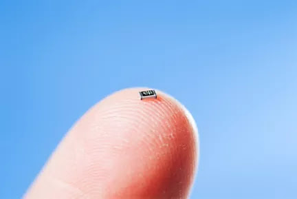
EM crosstalk is a big concern for engineers because of the demand for
electronic systems to increase in bandwidth and decrease in size. This
puts high-speed circuitry and high-bandwidth channels in proximity.
As electronics become smaller, crosstalk will become a bigger problem.
Additionally, the continuous increase in internal clock
frequencies (5 to 10 GHz) and the increase in data rates (above 10 Gbps)
are also fueling the emergence of crosstalk issues.
In short, fast speeds and small electronics create crosstalk;
consumer demands are creating SoC trends that make it impossible to
ignore parasitic inductance and inductive coupling.
There are many architectural and application design trends that contribute to crosstalk.
For instance, EM crosstalk is frequency dependent. However, engineers
cannot analyze EM crosstalk for a simple frequency of interest.
As an example, a clock signal with fast rise and fall times contains
significant harmonic frequency components. So, a clock running at 10 GHz
has a 5th harmonic frequency component running at 50 GHz.
Multiple ethernet lanes on the same system can become a crosstalk nightmare.
Those who target on-chip clock frequencies of 25 GHz, however,
will have to think about how to safely model the 3rd harmonic, which
falls into microwave frequencies.
EM crosstalk can affect signal
magnitudes, or noise level. Hence, the impact of crosstalk is further
exacerbated by the decrease in signal voltage levels and the increase in
sensitivity to noise driven by lower-power trends in SoC applications.
Ethernet,
fiber channel and peripheral component interconnects (PCI) can also be
sources of crosstalk. To achieve high data rates, these buses employ
multiple serial lanes that operate in parallel. For example, a 100 Gbps
ethernet can employ 10 channels that are each running at 10 Gbps. When
so many high-speed serial lanes reside in a single system, every lane
can be a potential aggressor or a potential victim — a true crosstalk
nightmare.
Other architectural trends that increase the likelihood of EM crosstalk include:
- High-speed analog blocks on one SoC
- Like phase-locked loops (PLLs) and voltage-controlled oscillator (VCO)
- Multiple high-speed clock networks on the same chip
- Clocks
don’t need to operate at high frequencies — victim clocks running at 10
GHz can be affected by aggressor clocks running at 2 GHz.
- RF or high-speed analog blocks adjacent to high-speed digital blocks
- Shared ground nets and silicon substrates can’t be tapped as a ground.
- Silicon substrate remains a key noise-propagation channel between blocks.
- Seal rings and scribe lines inserted by foundries
- Low power designs with small signal-to-noise margins
- Sensitive control/reset signals that can be set by crosstalk glitches
- Integrated fan-out wafer-level packaging techniques
- Multiple dies in proximity increase the likelihood of EM crosstalk.
Crosstalk Solutions
SoC integration places high-speed digital circuitry, analog, and
RF blocks close together and creates opportunities for crosstalk inside
those components and across various blocks.
Most electronic design
automation (EDA) tools are geared for a specific design type — such as
digital, analog, or RF component design. However, crosstalk is not
limited by these boundaries.
Ansys Pharos can help engineers identify crosstalk.
IC design engineers should be able to predict the coupling effects during the signoff phase. Using Ansys RaptorH IC, designers can accurately predict electromagnetic coupling effects and easily capture unknown crosstalk among different blocks in the design hierarchy.