Sunday, August 10, 2025

A Thoughtful and Comprehensive Approach to Teaching Simulation Across Undergraduate Engineering

In universities worldwide, students are discovering the transformative power of simulation and mastering its applications to tackle diverse challenges across industries. Simulation-based learning brings reality closer to the classroom, transforming the educational landscape and enhancing students' engagement with real-world scenarios.

Universities are expanding their engineering curricula to keep up with the ever-evolving world of modern engineering. Training future engineers in simulation is increasingly recognized as a vital component of professional development.

IMT Elevates Engineering Education

Mauá Institute of Technology (IMT) is a private, non-profit institute in São Paulo, Brazil, that gives engineering students the advantage of learning how to use simulation throughout their chosen program. IMT has provided students with leading educational opportunities in business management, design, and engineering for over 60 years. Its engineering department boasts nine different programs that range from food engineering to mechanical engineering. Students gain plenty of experience in using Ansys simulation tools thanks to support from the Ansys Academic Program and Ansys Apex Channel Partner ESSS.

Simulation Meets the Classroom

student-in-class 
Student working on a simulation in Ansys Fluent software during class.

IMT engineering programs are five years long and offer many opportunities for extracurricular courses and disciplines. With an Ansys Academic Multiphysics Campus-Wide Solution, the university has comprehensive access to Ansys simulation tools, enabling the integration of simulation across its engineering curriculum. In their second year, students traditionally have their first experience with Ansys simulation, beginning with Ansys Granta EduPack teaching software for materials education. Throughout the program, students add to their simulation skills with exposure to Ansys tools embedded into each engineering track.

Students gain years of experience in Ansys tools such as Ansys Fluent fluid simulation software, Ansys CFX computational fluid dynamics software, Granta EduPack software, and Ansys Mechanical structural finite element analysis software before they even enter the workforce. They are given opportunities to simulate challenges ranging from understanding the aerodynamics of airplanes and race cars to assessing the risk of brain aneurysms. In fact, simulation is such a highly requested and attractive feature of the program that IMT is now offering it as a “special project and activity” available to first-year students, and an elective discipline for senior students comprising a broader use of simulation in mechanical engineering.

Learning Through Numerical Simulation

Courses in programs like the mechanical engineering track are structured to enable students to study real-world phenomena central to industry applications. Students become well-versed in numerical simulation, particularly in mechanical, chemical, civil, and electrical/electronic engineering courses. For example, the mechanical engineering program involves stages that take the students from computer-aided design (CAD) problem modeling to geometry creation, mesh generation, setup, solution, and post-processing. Students complete even further steps of verification and validation when conducting numerical analyses.

maua-flow-around-a-circular-cylinder 
Demonstration of air flow around a circular cylinder in a wind tunnel.

“We start to teach numerical simulation in the third year … and as the years pass, we start to increase the difficulty level so they can study more complex problems,” says associate professor and course coordinator Dr. João de Sá Brasil Lima.

Engineering Education from Every Angle

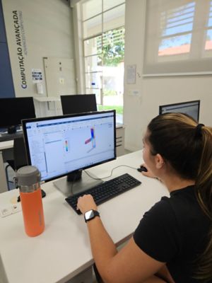
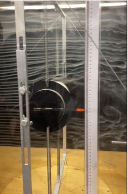
Thanks to the “360ᵒ approach” of IMT’s engineering department, students are gaining a better understanding of physical phenomena through hands-on modeling. Students study a theoretical problem using numerical simulation in both a classroom and laboratory setting, where they can see the problem in real time and focus on its experimental, numerical, and analytical aspects.

“We are not just giving the student an average experience with simulation," explains Dr. Joseph Youssif Saab Jr., energy and fluids professor at IMT. “We believe it really drives the understanding of concepts, which you can use for simulation and then validate with experimental testing. We are making sure students can deeply understand the concepts involved.”

maua-numerical-simulation 
A numerical simulation of flow around a circular cylinder carried out on Ansys Fluent software.

Simulation Sparks Engagement in Students

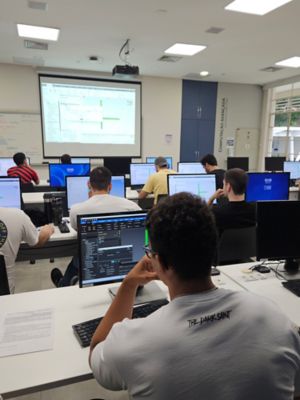
Undoubtedly, students at all levels of the program strongly favor the focus on simulation. “The students really like to use the tools during classes. They get more enthusiastic to study [phenomena] that previously were only taught on a blackboard,” says Lima. He shares that learning how to use Ansys tools helps capture students' attention, which enables them to better understand each tool's features. This knowledge equips students to understand and apply the appropriate tools when they enter the industry post-graduation, and an increasing number of students are seeing this happen sooner rather than later.

Student Teams

Students at IMT not only benefit from award-winning engineering classes, but also the opportunity to get hands-on experience through numerous student teams.

A well-known opportunity on campus is the MAUÁ Racing Formula SAE team. Formula SAE is an international engineering competition held in Michigan, organized by SAE International, where college students design, build, and compete with small formula-style race cars. The team from IMT took first place in the Engineering Design contest in 2024.

Taking Learning Beyond the Classroom

At IMT, it’s not uncommon to see 95% of graduating engineering students or more completing their programs with a job offer. Drs. Lima and Saab credit the multidisciplinary approach to teaching simulation — particularly numerical simulation — with keeping this employment number so high. Previously, employers would invest a great deal of time in training new employees in computer-aided engineering (CAE). IMT aims to increase the employability of its graduates by teaching them the skills they need to hit the ground running as new employees in any engineering field.

“We have introduced Ansys tools for problem-solving in many disciplines for many years now, and students are being selected by some industries based on this experience, in some cases, which is what we planned,” Dr. Saab says.

One student story in particular will always stick with the engineering staff at IMT: A student who oversaw numerical simulations for the MAUÁ Racing Formula SAE team as an extracurricular project made quite the impression on a new employer when he suggested they incorporate simulation into their workflow. After developing and proving a case for simulation, the employer was convinced that simulation could be the solution to several of their challenges. The student went on to start and run the first simulation department at that company, powered entirely by Ansys tools.

student-learning-simulation 
Students at IMT working in Ansys Fluent software during a lecture.

“One thing that really makes us happy is to see our students finish their program, go to companies to work, and still find new problems and situations that can be studied with numerical simulation,” says Dr. Lima.

Integrating Local Industry

IMT is not only sending its graduates out into the industry with an advanced simulation skillset, but it is also bringing the industry to the classroom. Engineering paths may vary, but it’s the shared use of simulation tools and comprehensive education that strengthens the IMT engineering department as a valued partner within the industry in Brazil and beyond. “We are developing partnerships in different ways,” Dr. Saab says.

A chemical plant component manufacturer has joined forces with IMT over the past five years to challenge up-and-coming engineers in a real-world scenario related to one of their products. In the challenge, an engineer from the company presents students every year with the geometry of the company's product. The students are then challenged to optimize the product using simulation, towards some specific final requirements. The engineer visits the class throughout the semester to check students’ progress on completing the challenge, then evaluates the final simulations and awards the team that reached the best results with a certificate signed by the company and IMT.

Another type of interaction happens within the HPA project, where the requirements are developed in-house, but engineers from an aircraft manufacturing company assess the results for each design team twice a year. This invaluable chance to gain hands-on experience and interact with industry professionals is just one example of how IMT raises the bar in simulation education.

Additionally, approximately 40 IMT students participate in the NAE Grand Challenges Scholars Program along with mentor professors from IMT, using Ansys simulation in research projects and beyond.

Pushing Boundaries in Engineering Education

Despite the impressive courses, collaborations, and research projects happening at IMT, the engineering department is always looking to advance the future of the program. Ultimately, the department aims to implement project life cycle management (PLM) into its catalog of existing tools. “If you can replicate the industrial environment inside your school, you can teach the students to go seamlessly into the industry without experiencing many differences,” Dr. Saab says. Professors of engineering at IMT are focused on finding the right solutions to further familiarize students with real-life industry experiences.

IMT continues to advance its role as a leader in engineering education by embedding simulation use into its programs. Just recently, IMT was awarded the highest grade (Grade 5) by the Brazilian Ministry of Education for its mechanical engineering courses. Additionally, IMT also obtained a Grade 5 among all mechanical engineering courses in Brazil (1st place in the Course Concept metric). “We are sure that our teaching in numerical simulation was one of the factors that contributed to these excellent results,” says Dr. Lima. By equipping students with these high-demand skills, the university continues to empower students to solve the complex challenges they will face in their careers.

Learn more about the Ansys Academic Program .

Cycling: Back in Action With Simulation

Any number of setbacks, such as a flat tire, a fall, or medical assistance, can cause a professional cyclist to fall behind the peloton. But once a rider reenters the race, they are often forced to expend an immense amount of energy trying to catch up to the pack.

This is especially problematic for team leaders, as losing ground can jeopardize the entire team’s strategy. To help preserve this cyclist’s energy, teammates will shield their team leader from the wind as he or she catches up to the peloton. But what configuration provides optimal wind coverage for the leader? As avid Tour de France fans, Professor Bert Blocken of Heriot-Watt University and his collaborators wanted to find out if they could use computational fluid dynamics (CFD) to quantify the benefits of different cycling formations.

figure-3-cropped 
High-resolution computational grid using the cyclist model developed by Heriot-Watt University and Ansys, part of Synopsys

Coming Out on Top

The Tour de France is not for the faint of heart. In the 2025 iteration of the world-famous race, cyclists covered over 3,000 kilometers — nearly 2,100 miles — over 23 days with a total elevation gain of 51,550 meters, or almost 170,000 feet. With climbs and summits in some of the most mountainous areas of France, riders need an unprecedented amount of physical and mental strength to come out on top.

Cycling may seem like an individual sport, but in reality, it heavily relies on teamwork. In the Tour de France, each of the 23 teams has eight cyclists who all play a crucial part in the overall success of the team. While each rider helps in different ways, the key to bringing the team leader back into the peloton is drafting. Teammates often form a paceline — a single file or staggered line — with their respective team leader sitting second to fifth in line. The goal of this strategy is to reduce drag for the leader by taking the brunt of the wind force.

“The main goal is to minimize the effort of the leader to preserve maximum energy for the rest of the race,” says Blocken. “Depending on the competitive situation, there will be the recruitment of one or more teammates to protect the leader as much as possible from the wind to reduce aerodynamic drag.”

Quantifying Formations With Simulation

Blocken and his collaborators published a study in which they investigated the effectiveness of different cyclist formations that shield the team leader from wind. Using a cyclist model developed by Heriot-Watt University and Ansys Fluent fluid simulation software, the team simulated the flow fields of wind around three, four, and five cyclists in varying formations. The researchers developed high-resolution computational grids with wall-adjacent cell sizes of 20 micrometers to resolve the important laminar sublayer at the cyclist and bicycle surfaces. The simulations were made with Fluent software using its advanced Transition SST k-w model in a pseudotransient formulation. In these simulations, they assumed there was no strong head, tail, or crosswind and that no in-race vehicles, such as cars or motorcycles, were present close to the cyclists. The results were then validated in a wind tunnel.

“We are bringing aerospace engineering technology to the Tour de France to help athletes better leverage their existing skills. But introducing artificial intelligence (AI) and numerical simulation into popular sports such as cycling is also an excellent way to show the importance of modeling and simulation to a wider audience and explain complex physics in a fun and simplified way,” says Thierry Marchal, program director, Sport and Healthcare at Ansys, part of Synopsys.

“The number of teammates required, and the configuration adopted to reduce the leader's effort without sacrificing too many team members, is usually determined by the current racing configurations and the feelings of the leader,” says Frédéric Grappe, head of performance and innovation at Equipe Groupama FDJ. “The ultimate goal is to bring the leader back into the group by smoothing out the effort as much as possible, avoiding accelerations as much as possible, which are very costly in terms of energy.” 

TUM Hyperloop Team Harnesses Simulation for Rapid Transportation

In a world where everything is expected to be faster — from smart devices to mobile networks — transportation is no exception.

The TUM Hyperloop team from Germany is made up of students and researchers supervised by their respective professors from the Technical University of Munich (TUM). As one of the top hyperloop development teams in the world, TUM Hyperloop’s goal is to change lives by transforming transportation as we know it. The team was created in 2015 for the SpaceX Hyperloop Pod competition and officially took the name “TUM Hyperloop” in 2017. In the competition, student teams were charged with creating the first hyperloop pods for high speed in partial vacuum. Fast-forward to 2025, and the TUM Hyperloop team now consists of nearly 30 students and engineers and is the creator of Europe’s first hyperloop segment certified for passenger mobility. And their goal? To engineer a world without limits of distance and time.

What is Hyperloop?

The innovative hyperloop system is divided into two components. It consists of an efficient network of tubes that connect mobility centers and on-demand vehicles, called pods, that move at an average speed of 600 to 900 km/h. The original concept of the hyperloop was much different than it looks now. The only thing that has stayed the same is that it involves a tube at a low environmental pressure, between 1 and 10 millibars.

TUM Hyperloop's design features a fully magnetic propulsion system with no moving mechanical components. The pod levitates magnetically inside a vacuum-maintained concrete tube, eliminating air resistance and enabling high-speed travel with minimal drag. This design not only improves efficiency but also enhances passenger comfort. Once implemented, the complete system will comprise multiple tube segments connected over long distances, allowing passengers to travel from point A to point B in record time.

thl-rollout 
A concept photo of a TUM Hyperloop pod.

What makes TUM Hyperloop’s design different from Japanese, South Korean, or Chinese maglev systems is their passenger vehicle concept. Current-day maglev systems are very similar to trains in that they both have multiple cars. The hyperloop system is different: each pod will hold between 20 and 50 people and be connected via a network of modular hyperloop hubs, similar to train stations. In addition to the style of car, the TUM Hyperloop team’s design is also different in that it is completely climate-neutral in operation. These advancements ultimately enable the system to operate with more frequent departures than conventional trains. The omission of mechanical contact, and ultimately wear and tear on parts, also greatly reduces downtime due to maintenance.

To achieve the most accurate atmosphere for test conditions, the team created a fully scaled demonstrator to serve as a test facility for passenger transport. The demonstration has been supported by the Bavarian State Government as part of the Bavarian High-tech Agenda, an initiative that seeks to boost science innovation in the region. In July 2023, TUM Hyperloop successfully performed the first passenger ride under vacuum conditions. In the test, two passengers experienced what a ride on the hyperloop would be like from the comfort of a passenger pod.

thl-demonstrator-2 
TUM Hyperloop demonstrator
 
thl-hub-boarding 
Conceptual image of the boarding zone of a hyperloop hub

Simulation Advances High-speed Transportation

We sat down with some members of the TUM Hyperloop team to learn about how they are leveraging Ansys tools, with help from an Ansys Student Team Partnership, to develop the technology for this ultra-fast, emission-free mobility network. The team has used Ansys simulation from the very beginning, according to TUM Hyperloop levitation engineer Oliver Kleikemper. “From what I heard from former colleagues, we tried a few simulation tools in the early days of the team and Ansys was the best choice … it has proven itself,” he says.

Since they began using Ansys tools, the team has relied on simulation throughout multiple disciplines within the Hyperloop design process.

Understanding Hyperloop Aerodynamics

João Nicolau, head of aerodynamics for TUM Hyperloop, explains that 100% of his team relies on Ansys simulation, mainly within Ansys Fluent fluid simulation software, along with the Ansys Fluent Meshing capability. The team also uses the Ansys Workbench simulation integration platform and Ansys Discovery 3D product simulation software for creating new conceptual designs. The ability to test the aerodynamics of the hyperloop not only saves time, but also enables the team to run tests with advanced physics modeling capabilities without the luxury of a multimillion-dollar test track. 

aerodynamics 
Ansys Fluent simulation showing the number of contours of the flow in the tube around the pod with supersonic flow in a pod-fixed coordinate system.

“That's the main challenge for aerodynamics — even small tests have severe limitations. It’s very costly in both money and in time, especially time because it needs to be very well prepared. And even if very well prepared, the results are still subject to the limited information we can get,” Nicolau says.

Looking ahead, the team plans to expand its use of Fluent software by integrating its capabilities with the finite element method (FEM), which would enable simulations to update one another in real time. This would lead to a more polished, informed design and ultimately a more advanced simulation.

Simulating the Structure, Electromagnetic Levitation, and Propulsion of Hyperloop Technology

The TUM Hyperloop levitation and propulsion teams rely on Ansys Maxwell advanced electromagnetic field solver for magnetic simulation to support their research and development of their hyperloop system.

Ansys simulation plays a crucial role in controller development for the electromagnetic suspension of the pod. The team relied heavily on the precise modeling capabilities of Maxwell software to provide them with the most accurate models.

levitation 
Concept study of a horizontal electromagnetic switch without moving components.

“Ansys accompanied our whole development process of the magnetic levitation system, from dimensioning the coils and magnets to studying their static and dynamic behavior,” says Kleikemper. “There has never been a big question if we should switch to another tool — it’s just very powerful.”

“There are a lot of mechanical and thermal simulations that we use Ansys for,” says Tim Hofmann, head of propulsion for TUM Hyperloop. As an example, the total mechanical deformation of the pod’s pressure vessel is shown below. The results of two construction methods are compared, where one is based on a frame with stringers, the other on a frame with rivets, also known from aircraft construction. 

structure 
Frame and stringer construction of the pod's pressure vessel. A simulation of the total mechanical deformation of the structure that is connected with frames, stringers, and additional clips. (left) A comparative study on the previous implementation of the pod's pressure vessel structure, in which the aircraft construction method with rivets and frames was simulated. (right)

Leveraging CADFEM’s Expertise With Ansys Solutions

The TUM Hyperloop team works closely with CADFEM Germany, an Ansys Apex Channel Partner. CADFEM is a pioneer in the application of numerical simulation in product development and a leading computer-aided engineering (CAE) provider, supporting Ansys users with all aspects of simulation.

Through seminars and workshops, the TUM Hyperloop team has taken full advantage of its partnership with CADFEM. “[CADFEM] is just someone who supports us in case there are questions and we need support. It’s very helpful and convenient when we are having a problem or when working with a new software,” explains Hofmann.

CADFEM not only provides the team with access to Ansys software licenses but also offers direct support for implementing tools as quickly as possible, enabling the seamless and fast integration of Ansys simulation.

What’s Next for TUM Hyperloop

As the team continues to advance and test their designs for the hyperloop network, they are looking to add more complexities to their simulations. Right now, the team is running most of their designs in 2D, which is already intensive. In doing so, they are shortening simulation runtimes from weeks to days. But there is more to do. The team plans to look to 3D simulations and high-performance computing (HPC) to help them both simplify and advance their workflow even further.

In addition to someday funding and building a full-size test track, the TUM Hyperloop team remains strongly involved in research and fostering student engagement.

Connecting Europe

“The European Commission and European High-tech developments want to build the hyperloop in Europe, so we continue to cooperate with different companies around Europe [and] reach an agreement on the general design so that it can be implemented in Europe,” says Nicolau.

Hofmann explains that now, with the local government, the European Commission, and the EU looking to develop a hyperloop reference track, the team is looking to establish a research group at TUM. “A very important point is us feeding information to the scientific community to make the system possible — we do provide a lot of valuable information. “We established a group at the university that is focused on research topics,” Nicolau says.

thl-vision

Looking to the Future of Sustainable Mobility

With the help of Ansys simulation and support from CADFEM, the TUM Hyperloop team is on their way to making the hyperloop system a reality. Through their pioneering advancements in sustainable mobility, the team is enabling more rapid transportation, greater passenger comfort, and more environmentally friendly methods to connect people faster than ever before.

See how you can power your team’s innovation with support from an Ansys Student Team Partnership.

Simulating at the Speed of Relevance: Next-Gen Technology Driving the CFD Industry

“Operating at the speed of relevance” is a United States national security maxim denoting the importance of responding to drivers of change in a flexible, agile, and intelligent manner.

This maxim has implications within the simulation sphere, as well, where simulation market leaders must respond quickly and flexibly when major technological developments — like advancements in graphics processing units (GPUs) and artificial intelligence (AI) — are changing the way simulations can be run.

Let's take a look at the next-generation technologies driving the computational fluid dynamics (CFD) industry, how Ansys is bringing these technologies into your software, and how you can leverage them to drive a positive change in your engineering workflows.

Watch the 2025 CFD Technology Trends: Leveraging AI, GPUs, and ROMs for Faster Engineering Insights webinar to learn more.

AI Is Enabling Rapid CFD Design Prediction

AI adoption in simulation has been steadily increasing, particularly in scenarios where creating and analyzing a vast quantity of data or design space is necessary. These scenarios can be seen in high-performance industries, such as automotive and aerospace, where extremely large models under tough environmental conditions need to be simulated to understand potential safety and reliability concerns. These models can generate vast amounts of data that need to be analyzed by an individual engineer or team and can be extremely time-intensive. Not to mention, there are times when running simulations can take longer than performing a physical test. This is not ideal, especially as a simulation can lose relevance if not turned around quickly.

AI is a good option to speed up data generation and data use in these large simulation model scenarios. AI can rapidly analyze vast quantities of data much faster than a single person, making AI tools for simulation a no-brainer to predict faster.

 
An introduction to the Ansys SimAI cloud-enabled artificial intelligence (AI) platform

The Ansys SimAI cloud-enabled AI platform enables you to leverage the accuracy of Ansys simulations with the predictive power of AI. This is a great timesaving and workflow efficiency tool that learns from your existing simulation data and generates optimized models quickly. The user experience (UX) also prioritizes simplicity for non-simulation experts, with no coding or data science expertise required. You simply upload your historical simulation data, select relevant performance metrics, and review the generated AI models to explore multiple design options and alternatives within minutes.

Our benchmark studies have shown that SimAI software can test design alternatives 10 to 100 times faster. This type of speed increase is a game-changer — not only for faster and more efficient workflows for engineers, but also for businesses where faster simulations can lead to faster design cycles and therefore an overall faster time to market.


"With Ansys SimAI, we will be able to easily test a design within minutes and rapidly analyze the results, ultimately redefining our digital engineering workflow and reshaping our perception of what is possible. By enhancing simulation speed, we can explore more technical possibilities during the upstream phase of our projects and reduce the overall time-to-market."

Renault

— William Becamel, Expert Leader in Numerical Modeling and Simulation, Renault Group

Source: Ansys Launches Ansys SimAI™ press release.


Leveraging AI is important for engineers and businesses to remain competitive and agile in a rapidly changing product development environment driven by tight deadlines and consumer demands.

Download our white paper to learn how you can assess new design performance in seconds.

ROMs and Data Fusion for Real-Time Simulation Throughout the Product Life Cycle

Reduced-order models (ROMs) are another AI-based tool that provides simplified representations of complex, high fidelity CFD models. ROMs are getting more popular as they are being used for different applications throughout product design life cycle.

rom-image 
Overview of a reduced-order model (ROM)

To create a ROM, engineers need to map model outputs to input excitations using training data generated through simulation or physical tests, or both. Once you have your training data, you can train your ROM so you end up with a lightweight model that runs in seconds with minimal storage requirements.

There are several scenarios throughout the product life cycle where ROMs can be used, including in bigger system models, digital twins, for transient or steady-state simulations, 1D-3D models, control software, and more. The real value is that ROMs will run in real-time, leveraging data-driven algorithms, while a CFD simulation with the same set of operating conditions can take significantly longer.

ROMs can also be enhanced and validated with data fusion, which ultimately reduces the need for extensive testing. Data fusion works by fusing two streams of data, typically a low-fidelity stream and a high-fidelity stream. When you combine the two, you end up with an accurate representation of your model while optimizing the time and cost.

ROMs can be used in early and late design cycles to improve product performance. ROMs are available in Ansys Fluent fluid simulation software with a CFD enterprise license.

Watch the 2025 CFD Technology Trends: Leveraging AI, GPUs, and ROMs for Faster Engineering Insights webinar to learn more.

Leveraging GPU Acceleration To Generate Data Quickly for AI and ROMs

AI and ROMs are both great tools to quickly understand and predict different design options, but they still require large amounts of data to work effectively. Generating data can take a significant amount of time, but we are seeing that time shorten through the recent advances in GPU-enabled CFD software.

For example, in the below DrivAer benchmark case, we saw a nearly 33x increase in solving speed when running Fluent software on eight NVIDIA A100 GPU cards compared against 80 Intel CPU cores. These GPU cards can be well worth the financial cost when they deliver exponential simulation speed increases.

speed-up-graph 
When running a benchmark DrivAer model on different CPU and graphics processing unit (GPU) configurations, our results show that a single NVIDIA A100 GPU achieved more than five times greater performance and almost 33 times greater performance when scaling up to eight NVIDIA A100 GPUs.

We’ve run some internal studies to help you determine the best and most financially sound GPU card options based on your design needs.

Combining GPU-acceleration with AI is the future; and it’s the solution that engineers and businesses should be prioritizing. GPU-accelerated CFD studies will generate simulation results exponentially faster, typically within a single working day. Feeding these results into a tool like SimAI software or using it to build high-fidelity ROMs will quickly provide potential design optimization strategies that can be passed along to manufacturing teams. Combining these technologies into one cohesive solution means that workflows that used to last weeks or months, can now be potentially completed in a few working days.

The future of CFD simulation is being shaped, and the businesses and engineers who adopt the technology accelerating CFD simulations will bring new and superior innovations to market faster. The fusion of AI, GPUs, and ROMs are paving the way for an exciting future in CFD where complex, large scale, high-fidelity simulations will take hours or days to run instead of weeks or months. Ansys is committed to helping you adopt, implement and successfully use all of these technologies to improve your workflows and bottom line.

Contact us to learn more.

A New Era of Ansys Fluent Computations: Billions of Cells, Minutes To Mesh, Hours To Solve

We have reached a new era in computational fluid dynamics (CFD) — one in which we no longer need to wait tremendous amounts of time for high-fidelity, scale-resolved simulation results. Waiting weeks or months is a thing of the past, and just ahead is an exciting future in which simulations can be completed within a single working day while still maintaining predictive accuracy. This is going to change how industries use CFD and will create ripple effects far beyond the simulation field.


Enabling the Next Generation of CFD With GPUs

Graphics processing units (GPUs) are fundamentally different than central processing units (CPUs). GPUs have a higher density of arithmetic logic units (ALUs), require lower energy to execute instructions, and have higher-memory bandwidth. Essentially, this means that you have significantly more computational horsepower at iso-hardware costs or iso-energy consumption.

The simulation market is adopting GPU technology, including Ansys Fluent fluid simulation software, to take advantage of the superior performance capabilities of GPUs. By running CFD simulations on GPU hardware, users can run more designs under more conditions in less time. Ultimately, this leads to creating more reliable products with fewer field failures at greater efficiency and sustainability.

A great example is the recent work that Ansys performed with NVIDIA and the Texas Advanced Computing Center (TACC). The partnership was created to run the DrivAer automotive benchmark model on a 2.4 billion-cell mesh. When running on 320 Grace Hopper superchips, Fluent software produced a staggering 110X speedup relative to the same model running on 2,000 CPU cores. Those 320 GPUs gave the incredible performance equivalent of more than 225,000 CPU cores. This breakthrough cut simulation time from nearly a month to just over six hours.

automotive-benchmark 
An automotive benchmark of a 2.4 billion-cell DrivAer dataset run on the Vista System at TACC with NVIDIA Grace Hopper GPUs

Of course, not everyone has access to NVIDIA Grace Hopper chips or TACC’s supercomputer. Still, you can see incredible simulation runtime improvements with more accessible GPU card options.

For example, using the same case as above with a smaller quarter-of-a-billion-cell mesh count, we reduced the simulation runtime from 52 hours (on 512 cores) to just 40 minutes on 64 NVIDIA L40 GPUs. NVIDIA L40 GPU cards are readily available and can be very cost-effective for some businesses, especially when considering the savings that can also be incurred from energy and electricity savings.

250m-cell-case-on-nvidia 
A 250 million-cell cell transient, scale-resolved case solved in just 40 minutes on 64 NVIDIA L40 GPUs
 
hw-cost 
A one-time purchase of eight NVIDIA A100s is about three times cheaper than purchasing the equivalent CPU cores necessary to run the model in the same amount of time.
 
electricity-cost 
Electricity costs are also significantly lower when running a job on eight NVIDIA A100s than the equivalent 12,000-plus CPU cores. (Electricity cost is estimated at about 0.13/kWh.)

Beyond just a pure performance benefit, GPU cards can also be more cost-effective from a purchasing and energy standpoint than CPUs. As shown above, the cost to run the same case as shown above on 12,288 CPU cores (the cores necessary to run in the same amount of time as 8 NVIDIA A100s) was around 3X more expensive. And when looking at the electricity cost of the job, the costs associated with running on CPUs are significantly more expensive than running on 8 NVIDIA A100 GPU cards.

Leveraging GPU hardware, even if it is not top of the line, can still result in some amazing benefits, not only for simulation solve time improvements but also hardware and energy savings.

Access the Ansys Fluent GPU Hardware Buying Guide to learn more.

Achieve Faster Preprocessing With Rapid Octree Meshing

Solving is just one portion of a simulation workflow, though often the most time-consuming. While we dramatically reduce solve times thanks to GPUs, the time spent preprocessing and meshing large, complex models is becoming increasingly substantial for models that require high levels of detail.

Fluent software offers a compelling solution with the rapid octree meshing method. Rapid octree meshing is a top-down meshing approach that is less sensitive to imperfections in the input computer-aided design (CAD) file than traditional, bottom-up meshing approaches. This enables a highly automated and scalable meshing preprocessing with minimal manual interaction while ensuring the geometry is still accurately represented.

As shown in the accompanying graph, as the number of cores increases, the meshing efficiency in terms of millions of cells per minute increases. Starting at 1,320 cores, the mesh for a complex nonreactive geometry is completed at 41.5 million cells per minute. At 3,960 cores, that number increases to 124 million cells per minute, giving a 99% scaling efficiency. This gives an overall meshing time of 30 minutes on 3,960 cores for a 3.7 billion-cell mesh.

Combining rapid octree meshing technology with our extremely fast GPU solver massively reduces the time to solution from end to end, enabling shorter design cycles, increased design exploration, and ultimately faster time to market.

rapid-octree 
Rapid octree mesh scalability for a 3.7 billion-cell mesh

Real-World Examples: Meshing and Solving in One or Two Working Days

1 Billion-Cell Combustor Simulation Solved in Just 28 Hours

In 2025 R1, Ansys introduced the flamelet-generated manifold (FGM) model into the Fluent GPU solver. This meant that engineers working on gas turbine combustion could now leverage the associated speedups for their simulations.

In the use case below, an efficient energy engine (EEE) full annular combustor was processed in just 16 minutes using rapid octree meshing technology on 1,536 CPU cores. The case was then run on the Fluent GPU solver using the FGM model with reacting flow and spray in 28 hours on 48 NVIDIA L40s.

 A 1 billion-cell EEE full annular combustor was meshed in 28 minutes and solved in 28 hours on 48 NVIDIA L40 GPUs.

What was once a “hero” calculation — one that takes massive computational resources and weeks or months to solve — is now becoming much more commonplace. By combining scalable meshing and GPU hardware, we are witnessing a step-change in CFD use across industries.

1 Billion-Cell Aircraft External Aerodynamics Simulation Solved in 30 Hours

Simulating external aerodynamics can be quite complex, requiring scale-resolving simulations (SRS) to accurately predict the acting forces. To achieve the required accuracy, cell counts must increase to capture the development and dissipation of turbulent structures. By using smaller cells to better resolve the surfaces and turbulence effects, the required time step size reduces, too. This leads to a substantial consumption of computational resources to improve designs even further.

With the Fluent GPU solver and rapid octree meshing method, the 1 billion-cell large eddy simulation (LES) of a high-lift aircraft was run in just 30 hours on 40 NVIDIA L40 GPUs. The mesh was generated in just 28 minutes on 512 CPU cores.

 
A 1 billion-cell LES of a high-lift aircraft solved in just 30 hours on 40 NVIDIA L40 GPUs

600 Million-Cell Jet External Aerodynamics Simulation Solved in 14 Hours

An external aerodynamic simulation of a fifth-generation jet was solved on 600 million cells in just 14 hours—an incredible solve time, considering the level of detail included in the simulation. The jet was meshed in 30 minutes using rapid octree meshing on 480 CPU cores and solved in just 14 hours on 20 NVIDIA L40 GPU cards using wall function LES.

 
A 0.6 billion-cell external aerodynamics simulation solved in just 14 hours on 20 NVIDIA L40 GPU cards

Customer Success Stories

Outside our internal benchmarking, customers who have adopted both rapid octree meshing and the Fluent GPU solver technology have seen great performance benefits resulting in massive time savings for their CFD simulations.

Baker Hughes

In April, Ansys, Baker Hughes, and the Oak Ridge National Laboratory set a supercomputing record on AMD Instinct GPUs, reducing simulation runtimes by 96% for a 2.2 billion-cell axial turbine simulation.

Compared to methods that utilize over 3,700 CPU cores, Baker Hughes and Ansys reduced the overall simulation runtime from 38.5 hours to just 1.5 hours using 1,024 AMD Instinct MI250X GPUs. This record-breaking scaling means faster design iterations and more accurate predictions, ultimately unlocking more sustainable technologies and products.

Volvo

In March 2025, Volvo announced that they reduced their total vehicle external aerodynamic simulations from 24 hours to just 6.5 hours using rapid octree meshing on CPUs and the Fluent GPU solver on 8 NVIDIA Blackwell GPUs — setting a benchmark in the automotive industry and beyond.

Leonardo Helicopters

Last year, Leonardo Helicopters adopted Fluent GPU solver technology to simulate the aerodynamics of helicopter rotors using LES. They not only saw a 2.5X reduction in their simulation runtimes but also an 80% reduction in energy use from 85 kWh to 15 kWh.

Seagate

In 2024, Seagate, a mass-capacity data storage company, utilized the Fluent GPU solver and NVIDIA GPU hardware to speed up the runtimes of their internal drive flow models. They saw a staggering 50X runtime improvement, with runtimes reduced from one month to less than one day.

Harnessing the Power of GPUs for Future Innovation

Ultimately, it’s widely known that simulation reduces design cycles and saves costs. The adoption of GPU hardware technology will help reduce these design cycles even further — from weeks or months to days, hours, or even minutes. A future in which simulations across all physics can be performed that fast is nearly here.

Discover how the Ansys Fluent GPU solver can speed up your simulations at the links below.

Learn More

How Ursa Major Is Advancing Propulsion for Aerospace and Defense

For years, propulsion technologies have enabled humanity to reach new frontiers by flying through the skies and exploring space. However, despite the importance of this cornerstone technology, its advancement has not been propelled to the forefront. Instead, propulsion has become a bottleneck in which demand exceeds the supply.

This challenge is conflated by the fact that propulsion technology is widely known to be costly, complex, and prone to causing launch failures, leading to hesitancy in making large changes to existing propulsion techniques and technologies.

It is within this environment that Ursa Major comes onto the scene. Ursa Major aims to power the future of defense and aerospace by providing advanced propulsion systems. To achieve this, the company has committed to leaving the tried and true behind by pushing hardware to its limits and iterating quickly to achieve much-needed advancements and innovations in propulsion. In doing so, the company is able to produce high-performance propulsion systems for commercial space, defense applications, and more.

ursa-test.png 
Testing an Ursa Major engine / Photo courtesy of Ursa Major

“Ursa Major's mission and vision has always been to develop propulsion,” says Bill Murray, chief engineering officer. “The idea has been that propulsion is a very expensive endeavor and requires a lot of expertise and knowledge. So, by condensing a lot of propulsion capabilities and expertise under one roof, you can reap the benefits of economies of scale.”

This strategy helps Ursa Major stand out. “Ursa Major is unique because we have experts in all the different disciplines that we're working in,” says Louis Villa, responsible engineer.

As part of this unique business model, Ursa Major also aims to move quickly and is OK with not getting a perfect solution every time. Instead, its goal is to reach an 80% solution, says development engineer Travis Thyes. With this approach, “after each test, we can go back and dissect what the learnings were, and we can continually roll those improvements into better and better products,” Thyes says.

Ursa Major’s multidisciplinary team and targeted approaches have led to innovations in propulsion technology that have the potential to power mission success across industries.

Exploring Ursa Major’s Propulsion Technologies

Ursa Major aims to help its partners by providing high-performance, competitively priced, and innovative turnkey rocket engines. To do so, the company relies on additive manufacturing (AM) to enable quick iteration, part commonality, modular production, surge readiness, and shorter build timelines. It uses a high-performance yet inexpensive oxygen-rich staged combustion cycle, performs extensive testing for reliability and performance, and prioritizes building reusable products.

ursa-major-engines.jpg 
Ursa Major engines / Photo courtesy of Ursa Major

Ursa Major also tailors its designs for multiple applications and engine sizes. This versatility results in several high-performing engine configurations:

  • Draper: a flexible liquid engine with storability that matches a solid motor
  • Hadley: the first oxygen-rich staged combustion engine produced in America
  • Solid Rocket Motors: Ursa Major’s solid rocket motors are additively manufactured and production-ready for all domains.

Using the benefits of these propulsion systems, customers across multiple sectors can achieve mission success.

The defense industry stands to benefit greatly from this technology. “Ursa Major sees itself as the cutting-edge development arm of the U.S. Department of Defense (DoD) right now,” says Murray. This collaborative relationship helps accelerate the company’s design process and create usable defense solutions for a wide range of missions.

Ursa Major is also helping drive progress in the space domain with satellite propulsion. Here, the company’s propulsion technology can enable reliable launch and in-orbit maneuverability solutions. For example, Ursa Major is developing a modular hydrazine in-space propulsion system that offers customized degrees of freedom for satellite control.

“At this point in the company's evolution, we're at a great point to start branching out into actual missions across a huge variety of spaces, commercial and defense,” says Murray. This progress comes with a few hurdles that Ursa Major is actively working to overcome.

Propulsion Challenges Faced by Ursa Major

At its core, propulsion is a challenging field. “Rocket engines are some of the most power-dense machines ever built by man,” says Murray. “What that means in practice is that every component of a rocket engine is stretched to its limits.”

The Ursa Major team is tasked with achieving the maximum performance possible from each part of its designs to achieve mission goals. At the same time, the team needs to consider factors like minimizing weight, reducing costs, and designing for reusability.

ursa-major-engine.jpg 
Ursa Major engine / Photo courtesy of Ursa Major

These challenges are heightened by Ursa Major’s goal to move rapidly. “We have to put a lot of effort into developing highly reliable and very effective products quickly,” says Villa. “It’s all about figuring out the intelligent shortcuts you can take to make sure that you're getting the best product to market as quickly as possible and in the hands of the people who need it.”

Additional challenges occur depending on the specific application of Ursa Major’s technology. For example, take in-orbit maneuverability for lengthy space missions, which is a critical yet complex function. Here, “one of the hardest parts is making sure that that propulsion system can work in a wide range of thermal conditions and over a long time period, measured in years or decades,” says Murray.

To face these challenges head-on, the Ursa Major team turned to simulation, working with Ansys Elite Channel Partner, PADT.

Propelling Ahead With Simulation

At Ursa Major, simulation acts as a sort of “guiding light,” says Thyes. The Ursa Major team uses Ansys software — including Ansys Mechanical structural finite element analysis software, Ansys CFX computational fluid dynamics software, and Ansys Fluent fluid simulation software — throughout its design and development process to increase efficiency in every part of its designs.

For example, simulation software enabled the team to iterate quickly before proceeding to the real-world testing stage, which requires purchasing costly hardware. “Simulation is really important for us because we want to be able to predict failures before we test something,” says Villa.

This way, Ursa Major can identify and understand potential issues before moving on to physical prototyping. “Simulation has been pivotal in making sure that we get really close to the final results on the first try,” Murray says.

This is particularly important for the complex problems Ursa Major works on, which involve working with many different materials with varying properties. As certain materials can cause issues if placed next to one another, “being able to recreate the environment and then the stresses that those different components see next to each other is very informative for our design process,” says Villa. Ansys simulation solutions enable Ursa Major to predict how components will interact with each other and then determine how to improve the performance of each individual component.

Simulation software can reduce costs in other ways, too, such as by enabling a streamlined team. “With modern software, we are able to reduce the number of people it takes to develop something, which means individuals can do way more than they used to be able to do,” Murray says. Customizing their simulation tools and analyses also “allows us to have a shared language when it comes to our analysis,” says Villa. “It allows anybody to look at the work that you did and […] understand the results and whether or not that component is going to work.”  

Simulation software proves especially valuable when designing for challenging missions, particularly those in space. “Generally, those problems can only be solved by analysis because you can't always test in space,” says Murray. “So, our analysis tools are really critical to making sure that the customer knows that our hardware will work, whether it's going from ground to space or staying in space for a long time.”

Throughout its history, Ursa Major has used simulation software to help pursue its vision. Ursa Major started with the goal of building a liquid rocket engine from scratch, and it achieved this with only six people. “That was only possible due to advanced software technologies,” says Murray. Today, simulation remains a critical tool for the Ursa Major team. “We wouldn't be where we are today without the computational power and the tools that we use to be able to develop engines as quickly as we do and as with as few people as we do,” says Villa.

How Ursa Major Is Growing and Adapting

When envisioning the future of Ursa Major, Villa sees two points of progression:

  1. Continuing to advance its existing engine designs
  2. Adapting its current engines or developing new ones to meet evolving market needs

One part of the latter goal will be adjusting to the growing space industry. “Space is the representation of a lot of great possibilities, exploration, and expansion,” says Murray. To keep pace with this growth potential, Ursa Major plans to expand its propulsion technology applications for new applications, like solid rocket motors.

As for achieving these goals, Ursa Major is very optimistic that these advancements will come to fruition.

“Over the next 10 years, I see Ursa Major providing engines for the growing both domestically and internationally,” says Murray.

Learn more about the how simulation is used in the space industry.

Best Practices To Optimize Infrastructure for Ansys Simulations

Ansys applications play a vital role in helping engineers evaluate and optimize product performance under real-world conditions. To fully realize their potential, these applications require robust computing infrastructure that can efficiently handle large, complex simulations.

To support this need, Ansys and Hewlett Packard Enterprise (HPE), an Ansys high-performance computing (HPC) partner, have developed a best-practices guide to use HPC for Ansys workloads. This resource outlines key challenges manufacturing users often face, along with practical guidance and recommended approaches to help maximize performance and avoid common pitfalls.

Selecting the Right HPC System and Architecture for Ansys Workloads

As Ansys simulations become more complex and integrated, choosing the right HPC system is critical to ensure performance keeps pace with engineering demands. The first step is evaluating whether current infrastructure meets business goals and requirements. Factors such as job turnaround time, available capacity, and system costs should all be considered. Workstations or aging servers may no longer provide sufficient power and performance, potentially slowing product development and limiting a model’s simulation scale.

Running Ansys simulations efficiently at scale requires hardware that delivers balanced compute, memory, and input/output (I/O) performance. Key requirements include high-core-count CPUs with strong memory bandwidth, large RAM capacity, and low-latency, high-bandwidth interconnects.

Modern processors like the AMD EPYC™ 9005 Series meet these demands through large caches, high memory throughput, and scalable architecture. When combined with optimized simulation software and remote visualization capabilities, they enable efficient execution of large-scale structural and multiphysics workloads.

High-performance storage is also essential to avoid I/O bottlenecks, especially for data-intensive simulations and frequent checkpointing.

figure-overview-of-hpe-amd-solutions-for-ansys-customers 
Example of key infrastructure components aligned with Ansys workloads

Benchmarking Ansys applications on modern HPC systems can help identify performance gaps and guide upgrade decisions. For example, HPE ProLiant servers with AMD EPYC™ CPUs have demonstrated up to 35% higher performance and 25% greater energy efficiency compared to previous generations. Application benchmarks also show substantial gains across key workloads; Ansys LS-DYNA nonlinear dynamics structural simulation software, for instance, delivers up to 82% faster performance on AMD-based systems versus alternative processors.

3cars-collision-2 
Simulation of a three-car collision by Ansys LS-DYNA nonlinear dynamics structural simulation software

When selecting system architecture, it is important to align hardware choices with solver characteristics and memory. CPU- and memory-bound applications like Ansys Mechanical structural finite element analysis software and LS-DYNA software benefit from high-core-count processors with large caches and fast dynamic random access memory (DRAM), such as AMD EPYC CPUs. Meanwhile, graphics processing unit (GPU) acceleration is increasingly valuable for Ansys Mechanical applications as well as memory- and compute-intensive tasks like computational fluid dynamics (CFD) simulations using Ansys Fluent fluid simulation software, which can significantly reduce runtime when paired with AMD Instinct™ GPUs and their high-bandwidth memory. With the Fluent GPU solver, simulations that once took weeks or months can now be completed in hours or days. And Ansys Mechanical software continues to advance heterogeneous computing with expanded support for AMD GPUs in 2024 and a mixed CPU-GPU solver in 2025 that significantly boosts speed, scalability, and memory efficiency.

For maximum flexibility, hybrid infrastructure models — combining CPU-only and GPU-accelerated nodes — allow compute resources to be allocated according to workload needs. Tailored environments like these help maximize throughput and efficiency while ensuring readiness for future Ansys workloads.

Best practice: Regularly evaluate infrastructure to ensure it meets the evolving demands of Ansys solvers. Modernize when needed to maintain scalability, efficiency, and performance.

Hybrid Cloud as a Deployment Strategy

While cloud computing is increasingly used for enterprise workloads, computer-aided engineering (CAE) presents unique challenges that require careful planning. Simulation workloads tend to be long-running, resource-intensive, and license-constrained. These factors can limit the cost-effectiveness of pure public cloud strategies, particularly when compared to running simulations on bare-metal infrastructure with predictable performance and resource control.

That said, hybrid cloud solutions offer a compelling middle ground. This could be a valuable solution when running burst workloads, evaluating new solver capabilities, or executing proof-of-concept studies without committing to permanent infrastructure expansion.

hybrid-cloud-environment 
Hybrid cloud environments combine on-premises infrastructure with cloud-based resources to flexibly support large-scale, compute-intensive simulation workloads.

Ansys customers can combine simulation workloads across cloud and on-premises systems, with consistent support for licensing, job scheduling, and performance monitoring. This deployment model ensures engineering teams can remain agile without compromising on security, data locality, or runtime predictability.

Flexible deployment options from HPE GreenLake allow companies of all sizes to access high performance infrastructure and run Ansys simulation workloads in a cloud environment. In one case, a customer boosted simulation workloads with 3x faster performance.

Best practice: Use hybrid cloud environments for burst capacity, artificial intelligence (AI) model training, and short-term simulation spikes. For long-term sustainability, prioritize infrastructure that provides control, security, and cost transparency.

Integrating AI-Augmented Simulation Into Engineering Workflows

AI is becoming an active part of engineering simulation. Ansys now offers AI-enhanced capabilities across several applications, including materials prediction tools. These features leverage machine learning to improve processes like design optimization, sensitivity analysis, and turbulence modeling.

With these advancements, simulation workflows increasingly rely on both CPU and GPU resources. Engineering teams must now consider how best to balance and allocate these resources to maximize efficiency across traditional simulations and AI-augmented tasks. This shift places new importance on infrastructure flexibility and unified management to support mixed workloads.

Best practice: Optimize infrastructure for a mixed workload environment. Use HPC systems with high-efficiency AMD EPYC CPUs to run traditional Ansys simulations and free up GPU capacity for AI-augmented tasks.

Balancing Simulation Performance and Sustainability

As sustainability becomes a strategic priority across industries, manufacturers face the challenge of meeting growing engineering demands without compromising environmental goals. Ansys simulations, while critical for product development, require powerful data center infrastructure, often with increasing capacity and energy use.

To address this, selecting hardware optimized for energy efficiency and throughput is essential. Manufacturers should focus on dense, high-performance cluster systems that offer advanced cooling capabilities and deliver strong throughput per watt, tailored to the needs of Ansys applications.

Processors like AMD EPYC offer up to 2.25x better energy efficiency compared to alternative servers. In real-world scenarios, customers have reported energy savings of up to 30% after upgrading to HPE servers with AMD CPUs. For the most demanding workloads, optional direct liquid cooling (DLC) further improves data center efficiency while maintaining high simulation capacity.

For teams new to HPC environments, a variety of resources are available to help engineers and IT teams adopt energy-efficient computing practices while supporting the performance needs of Ansys simulations.

Best practice: Choose dense, high-efficiency server systems with advanced cooling options and energy reporting. Look for vendor partners with a proven track record in sustainable engineering infrastructure.

Adapting Infrastructure To Meet the Growing Demands of Ansys Simulation

As Ansys expands to integrated multiphysics and AI-enhanced simulations, infrastructure must evolve to handle growing demands. This requires careful planning for solver scalability, mixed workloads, and long-term flexibility.

Ansys, HPE, and AMD provide a combined solution to help accelerate simulations and support future needs. For benchmarks, recommended configurations, and technical guidance, download the full guide, Best Practices for Ansys Engineering Innovation with Next-Gen CAE Infrastructure. Or join us at HPE Discover 2025 to see how Ansys and HPE are enabling engineers to innovate faster with flexible, high-performance, AI-ready HPC solutions.

HELMo Gramme Institute Applies Ansys Solutions in Industrial Digital Twin Project

Engineering professionals and researchers in Belgium are gaining hands-on experience with key technologies of the fourth and fifth industrial revolutions. The longstanding HELMo Gramme Institute and its research center HELMo Link, formerly known as CRIG, are participating in the Interreg Euregio Meuse-Rhine (EMR) Digital Twin Academy project. Interreg EMR projects are supported by the European Regional Development Fund. The project aims to train professionals and researchers in leading-edge technologies for industry with a focus on digital twins. According to the Digital Twin Consortium, digital twins are virtual representations of real-world entities and processes synchronized at a specified frequency and fidelity.

With the support of Infinite Simulation Systems, an Ansys Elite Channel Partner, and the Ansys Academic Program, project participants integrated Ansys multiphysics simulation and digital twin solutions to explore real-world industry challenges. As a result, they gained firsthand simulation experience while discovering the value of digital twin technology.

helmo-crig-project-logo

Considering Digital Twins for Industrial Applications

Participants completed use cases in collaboration with Belgian industrials, including a company that specializes in the design and integration of plant maintenance and multitechnical services like water loop treatment for industrial refrigeration and district energy networks. 

This study aimed to explore using digital twin technology to predict the operating conditions of a water loop cycle in accordance with external factors such as ambient temperature. Project teams would need to model water loop elements, including a heat exchanger. They would also need to review the data history of system operating conditions at different ambient temperatures. 

The second case involved a different company that manages the production and distribution of drinking water for local municipalities.

This study sought to model a water distribution network between two reservoirs that must balance each other according to their levels while considering hourly energy costs. To explore this scenario, participants would study a drinking water distribution model consisting of two tanks, valves, sensors, pumps, and pipes.

Aside from the thermal aspects of the second case, project participants discovered that the systems of both cases were similar. Consequently, they could take the same approach, using the same tools in both studies.

reservoir-diagram 
This diagram illustrates a water distribution network positioned between two reservoirs for the analysis of an industrial use case.

“Ansys specializes in numerical simulation using finite elements,” says Sarah Nyssen, a research coordinator and assistant professor at HELMo Gramme Institute. “It covers all the stages required for numerical finite element simulation: geometric processing, meshing, resolution, results processing, and optimization. The software offered is useful in a wide range of industrial fields, including mechanical engineering, energy, automotive, rail, aerospace, medical, electronics, and others.”

Applying Simulation and Digital Twins to Industry Use Cases

HELMo project participants used the Ansys Workbench simulation integration platform, which made it easier to manage several tools simultaneously, including Ansys Fluent fluid simulation software and the Ansys Twin Builder simulation-based digital twin platform.

“We considered a number of different multiphysics software packages and finally opted for Ansys, in particular the Ansys Twin Builder platform for the numerical twin and Fluent software to study the computational fluid dynamics (CFD) in the system,” says Sarah Nyssen.

Equipped with reduced-order modeling capabilities, the Twin Builder platform integrates the accuracy of physics models with insights from real-world data powered by artificial intelligence/machine learning (AI/ML) techniques.

For both studies, the team applied Ansys tools in five main steps:

1.     Create the overall process using basic components in the Twin Builder platform.

2.      Model the fluid dynamics of complex components using Fluent software.

3.      Using Twin Builder software’s reduced-order model (ROM) builder, create a simplified model of the asset and add it to the overall process.

4.      Export data from Twin Builder software, deploy the twin to interact with external equipment and entities using Ansys TwinAI AI-powered digital twin software, and create a standalone application using TwinAI software’s  comprehensive Python application programming interface (API).

5.      Compare simulation results with actual field data to validate the digital twin and determine if it can be connected to the plant for effective, real-time monitoring and control.


Did You Know?

Reduced-order models (ROMs) are simplifications of complex models that capture the behavior of source models, enabling engineers and designers to use minimal computational resources when examining a system’s principal properties.

ROMs have become a staple for industries that demand high-quality end products with shorter design life cycles.


first-use-case-heat-exchanger 
Project participants used Fluent software to simulate heat exchange then created a reduced-order model (ROM) using the Twin Builder platform. 

During the first use case, professionals and researchers used Fluent software to simulate heat exchange. Next, they observed an air-water exchanger in optimum condition and simplified the model as much as possible to create an appropriate ROM. Similarly, in the second use case, the participants used Fluent software to analyze the flow of a pump and build a simplified ROM using Twin Builder software.

“These application cases have enabled us to grasp another facet of the possibilities offered by digital twin [technology] if it is integrated into a solid, stable development structure,” says Sarah Nyssen.

second-use-case-pump 
Project participants performed flow analyses on a pump using Fluent software and created a ROM with Twin Builder software.

In addition, the project participants gained experience with functional mockup units (FMUs) and the functional mockup interface (FMI), a free standard that enables interoperability between different simulation tools. The FMI made it possible to easily transfer the heat exchanger and pump ROMs from Fluent software and the Twin Builder platform into other software as needed.

structure-architecture-diagram 
Project participants established a digital twin workflow and development structure using Ansys solutions.

Essentially, the project expanded the group’s concept of the digital twin process to include key elements like analysis, development structure, shareable data architecture, and monitoring — all of which commonly involve simulation and AI/ML integration.

Discover Digital Twins at Ansys

Ansys is dedicated to advancing the next generation of industrial engineering and democratization of simulation through innovative tools, techniques, and capabilities, including reduced-order modeling, AI/ML, and digital twin technology.

Learn more by exploring Ansys Digital Twin Solutions.

A Thoughtful and Comprehensive Approach to Teaching Simulation Across Undergraduate Engineering

In universities worldwide, students are discovering the transformativ...